1. High heat-generating devices plus radiators and heat conducting plates
When a few components on the PCB generate significant heat (fewer than 3), adding a radiator or heat pipe to the heating component can be effective. If temperature reduction remains insufficient, a radiator with a fan can enhance heat dissipation. When numerous heating devices are present (more than 3), a large heat dissipation cover or board is recommended. This is a custom heat sink designed according to the position and height of the heating devices on the PCB or a large flat heat sink with cutouts for different component heights. The heat dissipation cover integrates onto the surface of the components, contacting each to aid in heat dissipation. However, inconsistent component height during assembly and welding can reduce effectiveness. Typically, adding a soft thermal phase change pad on the component’s surface improves heat dissipation.
2. Heat dissipation through the PCB board itself
Currently, commonly used PCB boards include copper-clad/epoxy glass cloth substrates or phenolic resin glass cloth substrates, with a minor use of paper-based copper-clad boards. While these substrates offer excellent electrical and processing properties, their heat dissipation capabilities are limited.

1. As a heat dissipation path for high-heating components, it is almost impossible to rely on the resin of the PCB itself to conduct heat effectively; instead, heat must be dissipated from the surface of the component to the surrounding air. However, as electronic products advance into the era of miniaturization, high-density mounting, and high-heating assemblies, relying solely on the small surface area of a component for heat dissipation is insufficient. Moreover, the widespread use of surface-mount components such as QFP and BGA means that a significant amount of heat is transferred to the PCB. Therefore, improving the heat dissipation capacity of the PCB itself, which is in direct contact with the heating element, is the most effective solution.
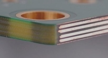
2. Utilize reasonable wiring design to achieve effective heat dissipation. Because the resin in the PCB has poor thermal conductivity, while copper foil lines and holes are good conductors of heat, increasing the copper foil area and adding thermally conductive vias are primary methods to enhance heat dissipation.
3. To evaluate the heat dissipation capacity of the PCB, it is necessary to calculate the equivalent thermal conductivity (κ_eq) of the composite material made up of various materials with different thermal conductivities, including the insulating substrate of the PCB.
4. For equipment that relies on free convection air cooling, it is best to arrange integrated circuits (or other devices) either vertically or horizontally.
5. Devices on the same printed board should be arranged based on their heat generation and dissipation characteristics. Devices with low heat generation or poor heat resistance (such as small signal transistors, small-scale integrated circuits, electrolytic capacitors, etc.) should be placed in the uppermost section of the cooling airflow, while devices with high heat generation or good heat resistance (such as power transistors, large-scale integrated circuits, etc.) should be positioned further downstream in the cooling airflow.
6. In the horizontal direction, high-power devices should be placed as close as possible to the edge of the printed board to shorten the heat transfer path. In the vertical direction, high-power devices should be placed as close as possible to the top of the printed board to minimize the temperature impact on other devices.
7. Temperature-sensitive devices should be located in the coolest area (such as the bottom of the device) and should never be placed directly above heating devices. Multiple devices should be arranged in a staggered horizontal plane if possible.
8. The heat dissipation of the printed board within the equipment mainly depends on airflow, so the airflow path should be considered during design, and devices or the printed circuit board should be configured accordingly. Airflow tends to move through areas of lower resistance, so avoid leaving large air gaps in any particular area on the PCB. Similarly, when configuring multiple printed circuit boards in a machine, this consideration should be applied.
9. Avoid concentrating hot spots on the PCB; instead, aim to distribute power evenly across the PCB to maintain uniform surface temperature performance. Although strict uniform distribution is often challenging, it is crucial to avoid areas with excessively high power density to prevent hot spots from disrupting the normal operation of the circuit. If possible, analyze the thermal efficiency of the PCB using thermal efficiency index analysis software modules available in some professional PCB design tools to optimize circuit design.
10. Place high-power and high-heat-generating devices near the best heat dissipation positions. Avoid positioning components with significant heat generation at the corners and peripheral edges of the PCB unless a heat sink is nearby. When designing power resistors, choose larger devices when feasible and ensure they have sufficient PCB heat dissipation space when adjusting the layout.
11. High heat dissipation devices should minimize thermal resistance to the substrate. To meet thermal characteristics requirements more effectively, use thermal conductive materials (such as a layer of thermally conductive silicone gel) on the chip’s bottom surface, maintaining a good contact area to aid in heat dissipation.
When a few components on the PCB generate significant heat (fewer than 3), adding a radiator or heat pipe to the heating component can be effective. If temperature reduction remains insufficient, a radiator with a fan can enhance heat dissipation. When numerous heating devices are present (more than 3), a large heat dissipation cover or board is recommended. This is a custom heat sink designed according to the position and height of the heating devices on the PCB or a large flat heat sink with cutouts for different component heights. The heat dissipation cover integrates onto the surface of the components, contacting each to aid in heat dissipation. However, inconsistent component height during assembly and welding can reduce effectiveness. Typically, adding a soft thermal phase change pad on the component’s surface improves heat dissipation.
2. Heat dissipation through the PCB board itself
Currently, commonly used PCB boards include copper-clad/epoxy glass cloth substrates or phenolic resin glass cloth substrates, with a minor use of paper-based copper-clad boards. While these substrates offer excellent electrical and processing properties, their heat dissipation capabilities are limited.

1. As a heat dissipation path for high-heating components, it is almost impossible to rely on the resin of the PCB itself to conduct heat effectively; instead, heat must be dissipated from the surface of the component to the surrounding air. However, as electronic products advance into the era of miniaturization, high-density mounting, and high-heating assemblies, relying solely on the small surface area of a component for heat dissipation is insufficient. Moreover, the widespread use of surface-mount components such as QFP and BGA means that a significant amount of heat is transferred to the PCB. Therefore, improving the heat dissipation capacity of the PCB itself, which is in direct contact with the heating element, is the most effective solution.
2. Utilize reasonable wiring design to achieve effective heat dissipation. Because the resin in the PCB has poor thermal conductivity, while copper foil lines and holes are good conductors of heat, increasing the copper foil area and adding thermally conductive vias are primary methods to enhance heat dissipation.
3. To evaluate the heat dissipation capacity of the PCB, it is necessary to calculate the equivalent thermal conductivity (κ_eq) of the composite material made up of various materials with different thermal conductivities, including the insulating substrate of the PCB.
4. For equipment that relies on free convection air cooling, it is best to arrange integrated circuits (or other devices) either vertically or horizontally.
5. Devices on the same printed board should be arranged based on their heat generation and dissipation characteristics. Devices with low heat generation or poor heat resistance (such as small signal transistors, small-scale integrated circuits, electrolytic capacitors, etc.) should be placed in the uppermost section of the cooling airflow, while devices with high heat generation or good heat resistance (such as power transistors, large-scale integrated circuits, etc.) should be positioned further downstream in the cooling airflow.
6. In the horizontal direction, high-power devices should be placed as close as possible to the edge of the printed board to shorten the heat transfer path. In the vertical direction, high-power devices should be placed as close as possible to the top of the printed board to minimize the temperature impact on other devices.
7. Temperature-sensitive devices should be located in the coolest area (such as the bottom of the device) and should never be placed directly above heating devices. Multiple devices should be arranged in a staggered horizontal plane if possible.
8. The heat dissipation of the printed board within the equipment mainly depends on airflow, so the airflow path should be considered during design, and devices or the printed circuit board should be configured accordingly. Airflow tends to move through areas of lower resistance, so avoid leaving large air gaps in any particular area on the PCB. Similarly, when configuring multiple printed circuit boards in a machine, this consideration should be applied.
9. Avoid concentrating hot spots on the PCB; instead, aim to distribute power evenly across the PCB to maintain uniform surface temperature performance. Although strict uniform distribution is often challenging, it is crucial to avoid areas with excessively high power density to prevent hot spots from disrupting the normal operation of the circuit. If possible, analyze the thermal efficiency of the PCB using thermal efficiency index analysis software modules available in some professional PCB design tools to optimize circuit design.
10. Place high-power and high-heat-generating devices near the best heat dissipation positions. Avoid positioning components with significant heat generation at the corners and peripheral edges of the PCB unless a heat sink is nearby. When designing power resistors, choose larger devices when feasible and ensure they have sufficient PCB heat dissipation space when adjusting the layout.
11. High heat dissipation devices should minimize thermal resistance to the substrate. To meet thermal characteristics requirements more effectively, use thermal conductive materials (such as a layer of thermally conductive silicone gel) on the chip’s bottom surface, maintaining a good contact area to aid in heat dissipation.


