The power supply is the most critical component of any electronic device. Any instability or malfunction in this section can cause the device to malfunction or behave unexpectedly. In this article/video, I introduce an AC to DC Flyback Switching power supply that converts 220V AC to 8V DC, suitable for a wide range of applications. The 8V output is ideal for powering linear regulators, making it highly versatile.
This power supply delivers a maximum output of 24W, capable of supplying 3A at 8V. The controller chip used is the DK125, which simplifies the design by not requiring any external power supply, startup resistor, or additional winding on the transformer. The transformer features an RM8 ferrite core, unlike most power supplies that use EE or EI cores. A small potentiometer is included to adjust the output voltage, allowing you to fine-tune it between 7.5V and 8V.
For the schematic and PCB design, I used Altium Designer 23 and shared the project with my colleagues via Altium-365 for feedback and updates. The Octopart component search engine was indispensable for quickly obtaining component details and generating the Bill of Materials (BOM). For high-quality PCB fabrication, I sent the Gerber files to wellcircuits.
Testing of the board included voltage drop, current delivery, output noise, and load step response measurements. The instruments used were the Siglent SDL1020X-E DC Load, Siglent SDS2102X Plus oscilloscope, Siglent SDM3045X multimeter, and Siglent CP4020 current probe. I am confident this power supply will meet your needs for a compact, efficient, and reliable solution on your electronics bench.
Download the Gerber files or order 10 high-quality boards for just 5 USD
To order a fully assembled PCB (including free shipping), click here
Specifications
Input Voltage: 85-265 VAC
Output Voltage: 8 VDC
Maximum Output Current: 3A
Continuous Maximum Output Current: 2.5A
Output Noise (No load): 4mV(rms), 18mV(p-p)
Output Noise (Max Load, 3A): 9mV(rms), 58mV(p-p)
Maximum Voltage Drop (3A load): 20mV
Transformer Type: RM8
Circuit Analysis
Figure 1 shows the schematic diagram of the power supply. The controller chip, DK125 [1], simplifies the design by eliminating the need for a complex transformer or additional components.
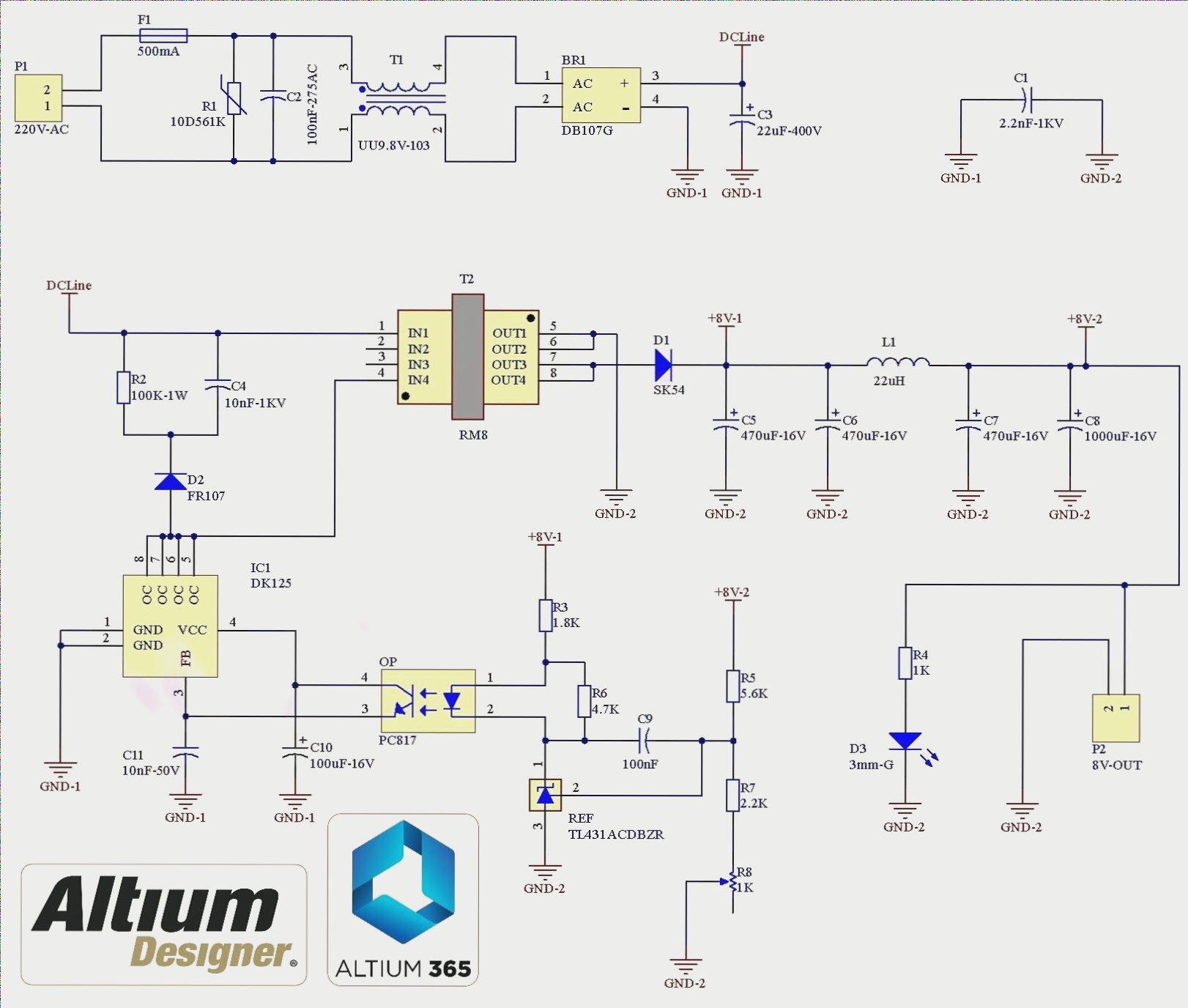
Figure 1
Schematic diagram of the 220V to 8V flyback switching power supply
P1 is a screw terminal for connecting the mains input to the board. F1 is a 500mA fuse for protection. R1 is a varistor that protects the circuit from transient voltage spikes, and C2 is a 100nF X2-rated capacitor [2] to suppress high-frequency noise. T1 is a 10mH common-mode choke [3] to filter out common-mode noise. BR1 is the DB107 [4] bridge rectifier to convert AC to DC, and C3 is a 22uF-400V electrolytic capacitor [5] to smooth out the ripple.
T2 is the RM8 ferrite core [6], on which you will wind both the primary and secondary windings. Figure 2 shows the RM8 ferrite core.
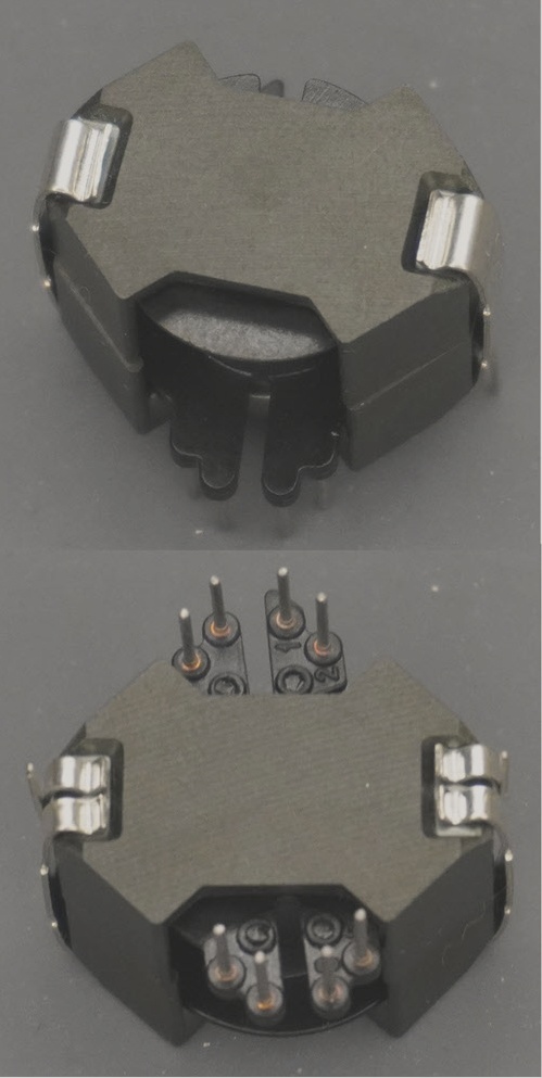
Figure 2
RM8 Ferrite core (4+4 Pin Bobbin, Ferrite Material: N87)
R2, C4, and D2 form the snubber circuit, which limits the reflected voltage from the transformer to below 120V. The DK125 controller chip integrates all the necessary components for a flyback power supply, including the MOSFET. D1, L1, C5, C6, C7, and C8 are part of the output rectifier and filtering system. D3 is an 0805 yellow LED [7] that indicates when the output voltage is within the acceptable range.
The feedback control loop includes the TL431ACDB voltage reference chip [8] for stabilizing the output voltage, and the PC817 [9] optocoupler that provides an isolated feedback path to the controller.
PCB Layout
Figure 3 shows the PCB layout of the design, which uses a two-layer board with both through-hole and SMD components. Figure 4 displays the assembly drawings.
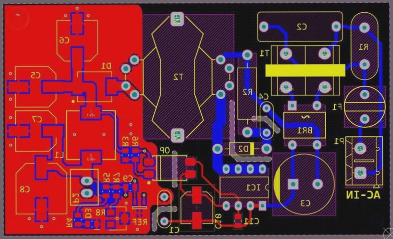
Figure 3
PCB layout of the flyback 220V to 8V 3A power supply
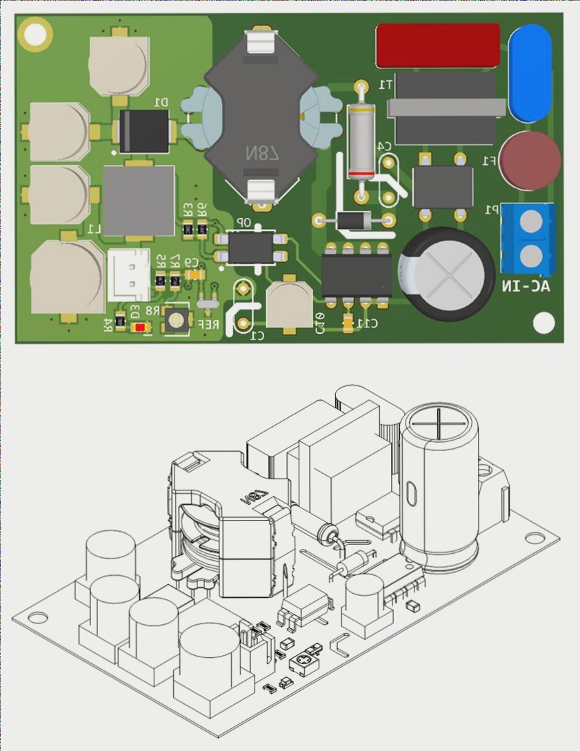
Figure 4
Assembly drawings of the flyback 220V to 8V 3A power supply
Transformer
To build the transformer, gather the following materials:
1. An RM8 ferrite core with its bobbin (4+4 Pin Bobbin, Ferrite Material: N87)
2. 0.26mm insulated copper wire
3. 0.8mm insulated copper wire
4. Transformer tape
The primary winding consists of 80 turns of 0.26mm wire wound clockwise. Refer to Figure 5 for the winding direction (left winding).
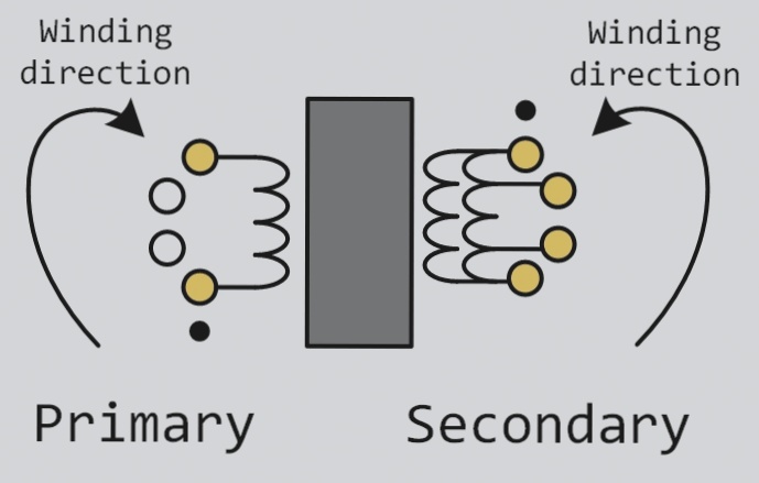
Figure 5
Transformer winding
Once the primary winding is complete, place the ferrite core in position and measure the inductance. The target inductance value for the primary winding is 2.5mH. You may need to grind the middle leg of the ferrite core while measuring inductance to reach the required value. Once achieved, cover the primary winding with two layers of transformer tape.
The secondary winding consists of 4 turns of 0.8mm*2 wire (two 0.8mm wires in parallel) wound counterclockwise. Refer to Figure 5 for the winding direction (right winding).
Ensure the wire tips are properly soldered to the bobbin pins and that there is

