AC Inrush Current Limiter: Protect Your Industrial Equipment
Dealing with damaging inrush currents on your industrial equipment? Consider using an AC inrush current limiter (soft starter) to mitigate these issues. Inrush current, also known as surge current, can harm equipment and lead to costly downtime. An AC inrush current limiter helps by limiting the initial current flow, ensuring a smooth startup and protecting your machinery.
This AC soft starter comes with an integrated fail-safe mechanism designed by Hesam Moshiri. The inrush current passes through a power resistor during startup, and after an adjustable delay, a 30A power relay bypasses the resistor to provide full power to the load. In case of relay failure, the power resistor prevents further damage. Three LEDs indicate Supply, Normal, and Fault conditions, with the controller using the low-cost ATTiny13 MCU.
For schematic and PCB design, Altium Designer 23 was used along with Octopart for component information. Wellcircuits provided high-quality PCBs based on Gerber files. The MCU code was written using the Arduino IDE for easy understanding.
Explore the schematic diagram of the 30A AC Soft Starter below:
Schematic Analysis
Figure 1 displays the core components of the circuit, with the ATTiny13 microcontroller playing a central role.
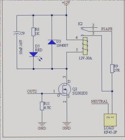
Figure 1: Schematic diagram of the 30A AC Soft Starter (Inrush current limiter)
From the top of the schematic, key components include the AC-IN connector, varistor for voltage spikes suppression, AC-to-DC module, potentiometer for delay adjustment, and various resistors and capacitors for circuit stability.
PCB Design
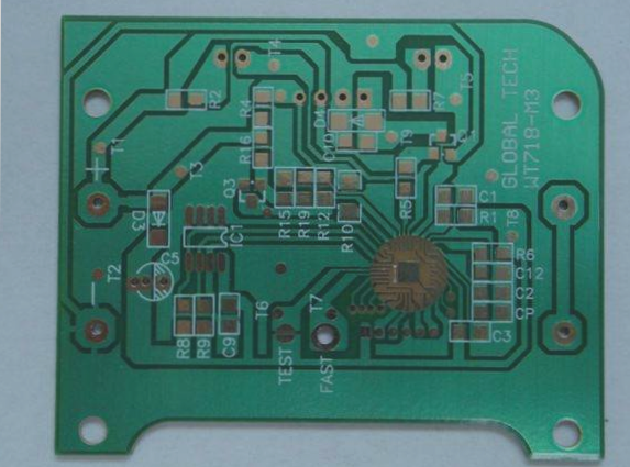
Check out the PCB layout of the design in Figure 2. This two-layer PCB features a mix of SMD and through-hole components, with a focus on clear separation between power and logic circuits for optimal performance.
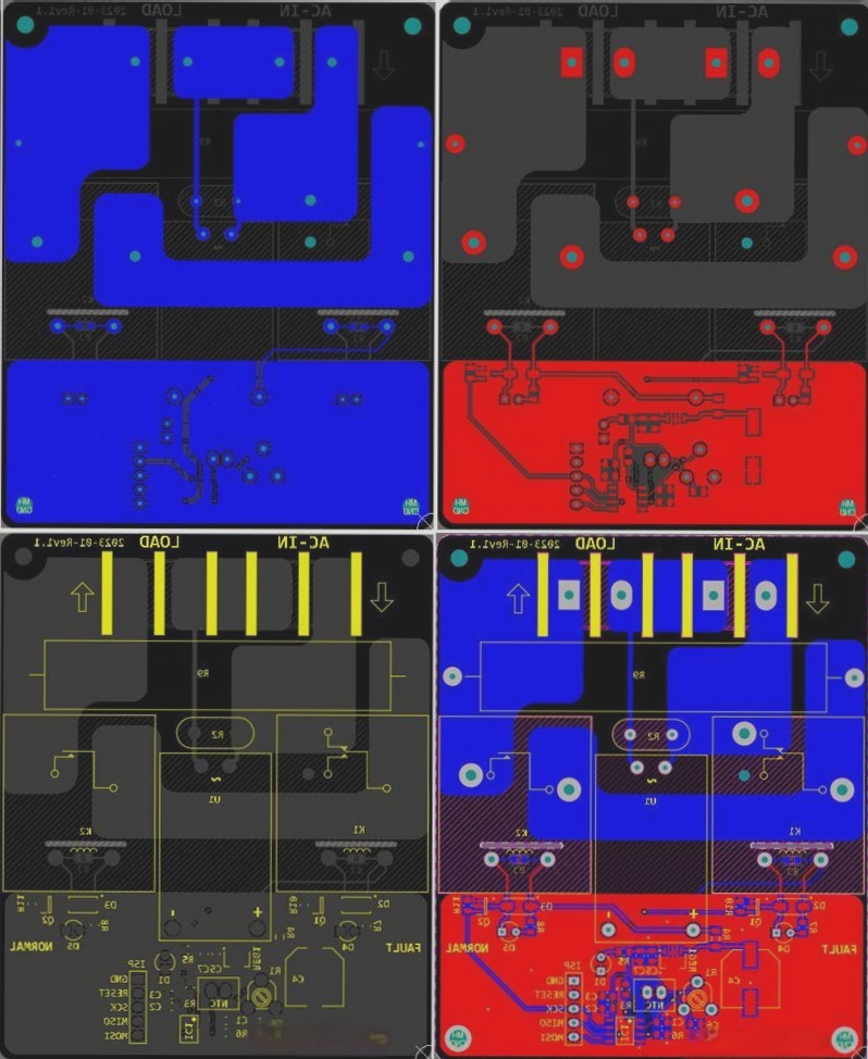
Figure 2: PCB layout of the 30A AC Soft Starter (Inrush current limiter)
Efficient Code Implementation
Programming the MCU on Your PCB
If you’re looking to program the microcontroller unit (MCU) on your printed circuit board (PCB), here’s a simple guide to get you started.
Firstly, use the Arduino IDE to write and compile the code for the MCU. You can install the MicroCore library to support ATTiny13, and the compiled HEX file is available for download.
Once you have the code ready, connect your programmer to the ISP header on the PCB and upload the code. Remember to set the fuse bits for the 9.6MHz internal clock and disable the clock division (DIV8).
If you wish to make changes to the code, here is a snippet for you to modify:
#define Relay1 1
#define Relay2 2
analog_pin_t potDelay = A3;
analog_pin_t NTC = A2;
unsigned int rawTemp = 0, rawPot = 0, delayms = 1;
unsigned char counter = 0;

void setup() {
  pinMode(Relay1, OUTPUT);
  pinMode(Relay2, OUTPUT);
  digitalWrite(Relay1, LOW);
  digitalWrite(Relay2, LOW);
}

void loop() {
  rawTemp = analogRead(NTC) + rawTemp;
  rawPot = analogRead(potDelay) + rawPot;
  counter ++;
  if (counter == 10) {
    rawTemp = rawTemp / 10;
    rawPot = rawPot / 10;
    delayms = map(rawPot, 0, 1023, 1, 1000);
    delay(delayms);
    digitalWrite(Relay2, HIGH);
  }
}
Enhancing Your PCB Project
For a more advanced PCB project, consider incorporating sensor data processing, wireless communication capabilities, or even cloud connectivity to take your project to the next level.
Remember to always test your PCB thoroughly before deployment to ensure its functionality and reliability.