DC-to-DC Converter Circuit: Buck Converter Design
A DC-to-DC converter is a common circuit in electronics, especially for power supply applications. The three main types of non-isolated DC-to-DC converters are Buck, Boost, and Buck-Boost. A buck converter, also known as a step-down converter, decreases input voltage while increasing output current.
This article/video showcases an adjustable buck converter circuit that can handle up to 30A and input voltages up to 40V. The output voltage can be adjusted from 3V to 37.5V. The design incorporates various PCB optimization techniques to enhance output stability, current handling, and reduce noise levels.
When creating the schematic and PCB layout, Altium Designer 22 and the Octopart electronic search engine were utilized to source the necessary components efficiently. To ensure quality, the Gerber files were sent to WellCircuits for fabrication, and performance testing was conducted using the Siglent SDL1020X-E DC load, Siglent SDM3045X multimeter, and Siglent SDS2102X Plus oscilloscope.
Key Specifications:
- Input Voltage: 6-40VDC
- Output Current: Up to 30A (continuous, see details)
- Output Voltage: Adjustable from 3V to 37.5VDC
- Output Noise: 50mVpp, 4mVrms (at 18A load, 20MHz bandwidth)
Explore Further:
- To inquire about fully assembled PCB boards (with free shipping), contact: info@wellcircuits.com
Circuit Analysis:
Figure 1 illustrates the schematic of the 40V-30A Adjustable Power Supply (Buck Converter). The primary components include IC1: UC3843 and IC2: IR2104. UC3843 was chosen for its efficiency at 12V, suitable for the MOSFET driver IC (IC2). Various components in the circuit aid in noise reduction and stable operation.
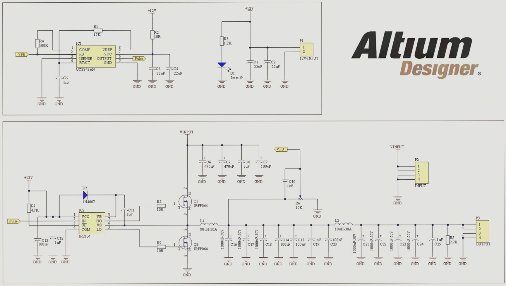
Figure 1: Schematic diagram of the 40V-30A Adjustable Power Supply (Buck Converter)
IC2, the IR2104 MOSFET driver, controls the half-bridge configuration with components like R5, R9, and essential capacitors for noise suppression. The circuit design ensures stable output voltage within the specified input voltage range.
L1 and L2 Inductors:
The L1 and L2 inductors utilize a green-blue toroidal iron powder core for efficient operation.
L1 Core Specifications:
- Outer Diameter: 51mm
- Inner Diameter: 24mm
- Ring Height: 22.5mm
- Inductance (no current): 80µH (minimum)
L2 Core Specifications:
- Outer Diameter: 33mm
- Inner Diameter: 19.5mm
- Ring Height: 11.2mm
- Inductance (no current): 10µH
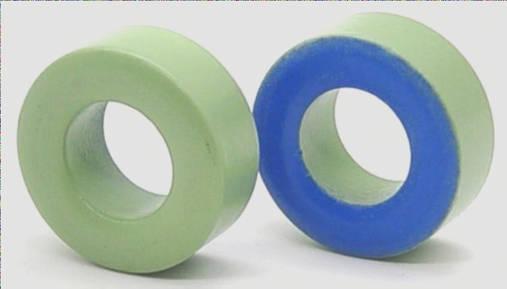
Figure 2
Appearance of the L1 and L2 Toroidal Iron Powder Cores
Circuit Board Layout
When designing the circuit board, a double-layer PCB layout was implemented, utilizing a mix of surface-mount device (SMD) and through-hole components. The assembly drawings of the board can be seen below:
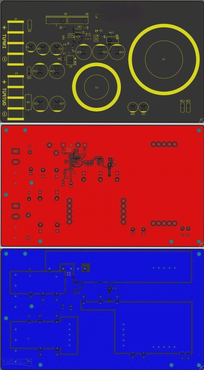
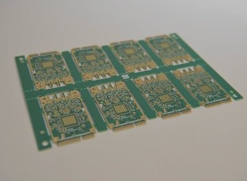
Figure 3: PCB layout of the 30A-40V DC-to-DC buck converter
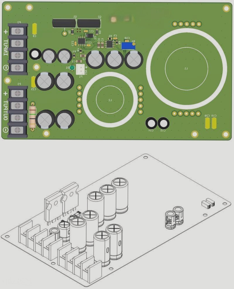
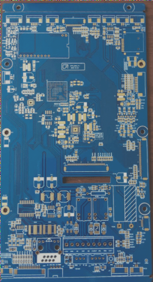
Figure 4: Assembly drawings of the PCB board
Assembly and Testing
After assembly, the PCB board should resemble the image below. For those short on time, fully assembled boards (excluding inductors) can be ordered. It’s essential to have a regulated 12V supply connected to the P1 connector, with the ground of the supply and the input voltage (P2 connector) connected in common.
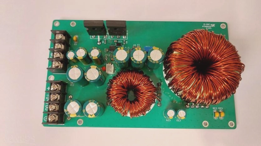
Figure 5: Assembled PCB board of the 30A-40V adjustable switching power supply (DC-to-DC buck converter)
When testing power supplies, it is crucial to assess regulation and output noise. To conduct these tests, I utilized the Siglent SDL1020X-E DC load, Siglent SDS2102X Plus oscilloscope, and Siglent SDM3045X multimeter. Testing was performed up to 18A, as demonstrated in the accompanying YouTube video. The power supply exhibited stable performance at this load.