Component placement
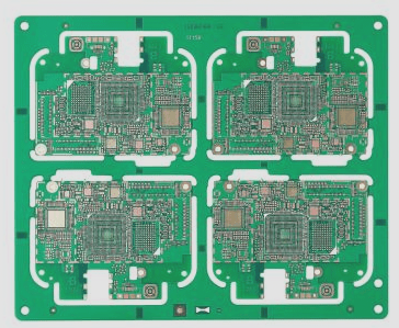
In addition to positioning decoupling capacitors, there are other considerations for placing components on a circuit board. Here are some guidelines:
1. If the circuit includes inductors, they should not be placed too closely together. Inductance produces a magnetic field, so placing them in close proximity, especially in an end-to-end configuration, may result in unwanted coupling between them. Also, inductors should not be placed near large metal objects as the magnetic field can induce current in these objects, affecting the inductor’s performance. Ring or toroidal inductors typically produce minimal stray magnetic fields.
2. If it is necessary to position inductors close to each other, they should be placed perpendicular to minimize mutual coupling. When the board features power resistors or components that generate significant heat, consider the impact of heat on nearby components. For example, a thermistor used for ambient temperature compensation should not be placed near power resistors. The same applies to temperature compensation capacitors.
3. If an on-board switching regulator is present, all associated components should be grouped together on a section of the PCB, away from areas handling small signals. Switching regulators tend to produce high levels of noise, which can interfere with sensitive circuitry.
4. When AC power is directly applied to the PCB in the power section, ensure the AC components are clustered in one part of the board. Additionally, include a physical barrier on the PCB to separate the AC section from the rest of the circuit. This is often accomplished by incorporating a slot in the PCB to create a division between the two sections.