Building a High-Performance DC Motor Driver
DC motors find extensive use in various fields, from hobbies to industrial applications, creating a demand for reliable motor drivers. This guide will walk you through constructing a versatile driver compatible with microcontrollers, Arduinos, Raspberry Pis, or PWM generator chips. The circuit, with proper cooling, can manage currents up to 30A.
Circuit Analysis
The heart of the circuit is the IR2104 MOSFET driver chip, known for its high-voltage, high-speed capabilities. The schematic, depicted in Figure 1, showcases the powerful DC motor driver.
Key features of the IR2104 include high and low-side output channels, compatibility with various logic signals, and the ability to drive MOSFETs or IGBTs in high-side configurations between 10V and 600V.
- The IR2104 drives MOSFETs in a half-bridge setup, effectively managing high input capacitance.
- Capacitors C1 and C2 reduce motor noise and EMI, with a recommendation for 100V-rated capacitors.
- The SD pin requires a 4.7kΩ resistor for proper function, and a steady logic voltage activates the chip.
PCB Design
Figure 2 displays the optimized PCB layout for stability and reduced noise in operation. Utilizing SamacSys components for IR2104 and IRFP150 streamlines the design process.
For component selection, SamacSys offers a convenient “component search engine” or CAD plugin, like the Altium plugin shown in Figure 3.
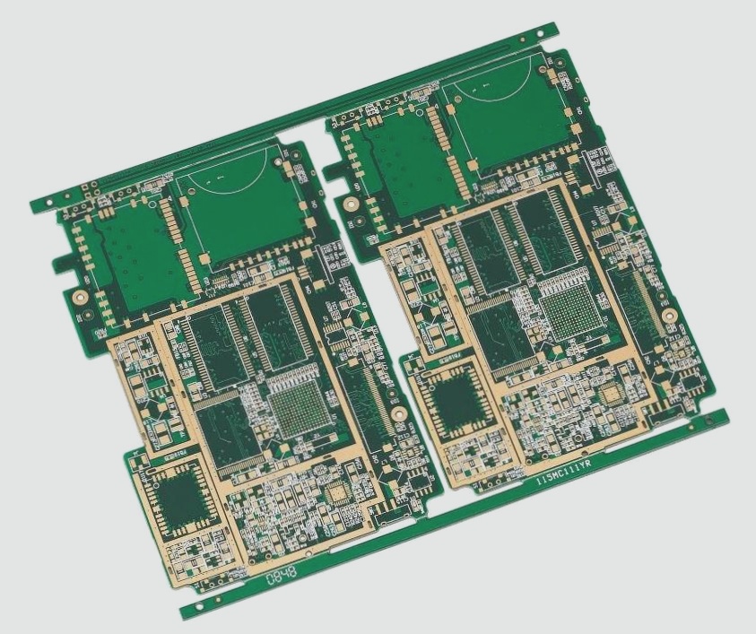
Additionally, a 3D view of the PCB (Figure 4) aids in component placement verification and board inspection.
Assembly
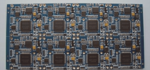
For initial testing, a semi-homemade PCB (Figure 5) expedites component assembly. Understanding the circuit’s functionality allows for ordering a professional PCB for comprehensive testing.
Figure 6 illustrates the bottom view of the assembled PCB, highlighting tracks requiring additional copper support due to handling significant currents.
Enhancing PCB Tracks with Copper Wire
Standard PCB tracks may not handle high currents well, risking overheating or damage. To reinforce them, consider soldering thick bare copper wire onto exposed areas (refer to Figure 7). This simple technique boosts the track’s current capacity without expensive alterations.
Bottom View of Uncovered PCB Tracks
This image (Figure-6) displays the underside of a PCB prototype, emphasizing the exposed tracks.

Utilizing Thick Bare Copper Wire
Here is a visual representation (Figure-7) of a thick bare copper wire that can be used to enhance PCB tracks.

Testing and Measurement
A YouTube video demonstrates testing a PCB board with a car’s windscreen wiper DC motor as the load. The video showcases PWM pulse generation using a function generator and the correlation between the load’s current consumption and the PWM duty cycle.
Bill of Materials
Refer to Table-1 for the bill of materials required for the project.
References
- [1]: Infineon IR2104 Datasheet
- [2]: IRFP150N Datasheet
- [3]: Component Search Engine Link
- [4]: Component Search Engine Part
- [5]: Altium Designer Library Instructions
If you have any inquiries regarding PCBs or PCBA, please reach out via email at info@wellcircuits.com.