The Ultimate Standalone H-Bridge DC Motor Driver
The Full-Bridge (H-Bridge) is a popular driver circuit for controlling brushed DC motors, offering the unique ability to change the motor’s rotation direction effortlessly. Responding to demands, a compact and affordable standalone H-Bridge DC motor driver has been developed, eliminating the need for external controllers.
Key Features:
- Controlled by an ATTiny13 microcontroller
- Allows motor control in Forward, Stop, and Reverse modes
- Independent speed adjustment for forward and reverse directions
- Handles higher currents with low MOSFET ON-resistance
Recent Updates:
For the schematic and PCB design, Altium Designer 22 was utilized. The Octopart search engine facilitated component data gathering and BOM generation. High-quality PCB fabrication was entrusted to WellCircuits, using Gerber files. Testing involved repurposing a toy car motor with a powerful 775 DC motor and gearbox.
Specifications:
- Input Voltage (Motor): 8-40VDC
- Supply Voltage (Controller): 12VDC
- PWM Frequency: 25KHz
- Motor Control: Forward-Stop-Reverse
- Motor Speed: [0 to 100%] Forward, [0 to 100%] Reverse
To order a fully assembled PCB board with free shipping, contact info@wellcircuits.com.
Circuit Analysis:
Figure 1 illustrates the schematic of the standalone full-bridge DC motor driver, comprising the H-Bridge driver, microcontroller, and supply regulator.
Microcontroller: The ATTiny13 microcontroller (IC1) manages the H-Bridge section, with decoupling capacitors (C1, C2) for noise filtration. Potentiometers (P1, P2) adjust motor speed, while connectors (P3, P4) interface with a 3-position switch for direction control.
Supply Regulator: The 78L05 regulator chip (REG1) and components (R4, C6, D1, R5, C7, C8) maintain stable supply voltage.
H-Bridge Driver: The core driver component for motor control.
High-Power D2Pack IRF3205 MOSFETs in H-Bridge Circuit
- Q1 to Q4: High-power D2Pack IRF3205 MOSFETs make up the H-Bridge circuit.
- Diodes D4 to D7 provide protection against reverse inductive currents from the motor.
- Include diodes for added safety.
- R6, R7, R8, and R10 are current-limiting resistors for the gate pins.
- IC2 and IC3 are IR2104 half-bridge driver ICs.
- C12 and C13 are decoupling capacitors.
- R9 and R11 are pull-down resistors to prevent unwanted triggering of the driver ICs.
- C9 reduces supply noise from the motor, especially during startup.
PCB Layout
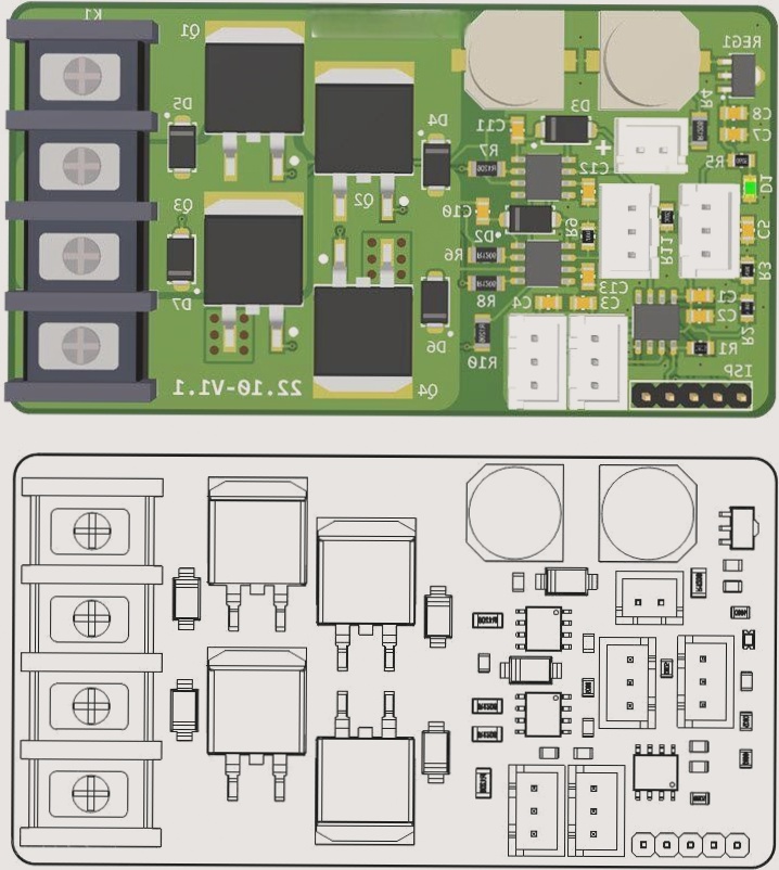
The PCB layout of the device is shown in Figure 3. It is a two-layer PCB with all SMD components, except for the connectors, making it compact and easy to integrate into enclosures. Assembly drawings of the PCB are illustrated in Figure 4.
Figure 3
PCB layout of the Standalone Full Bridge DC Motor Driver (Altium)
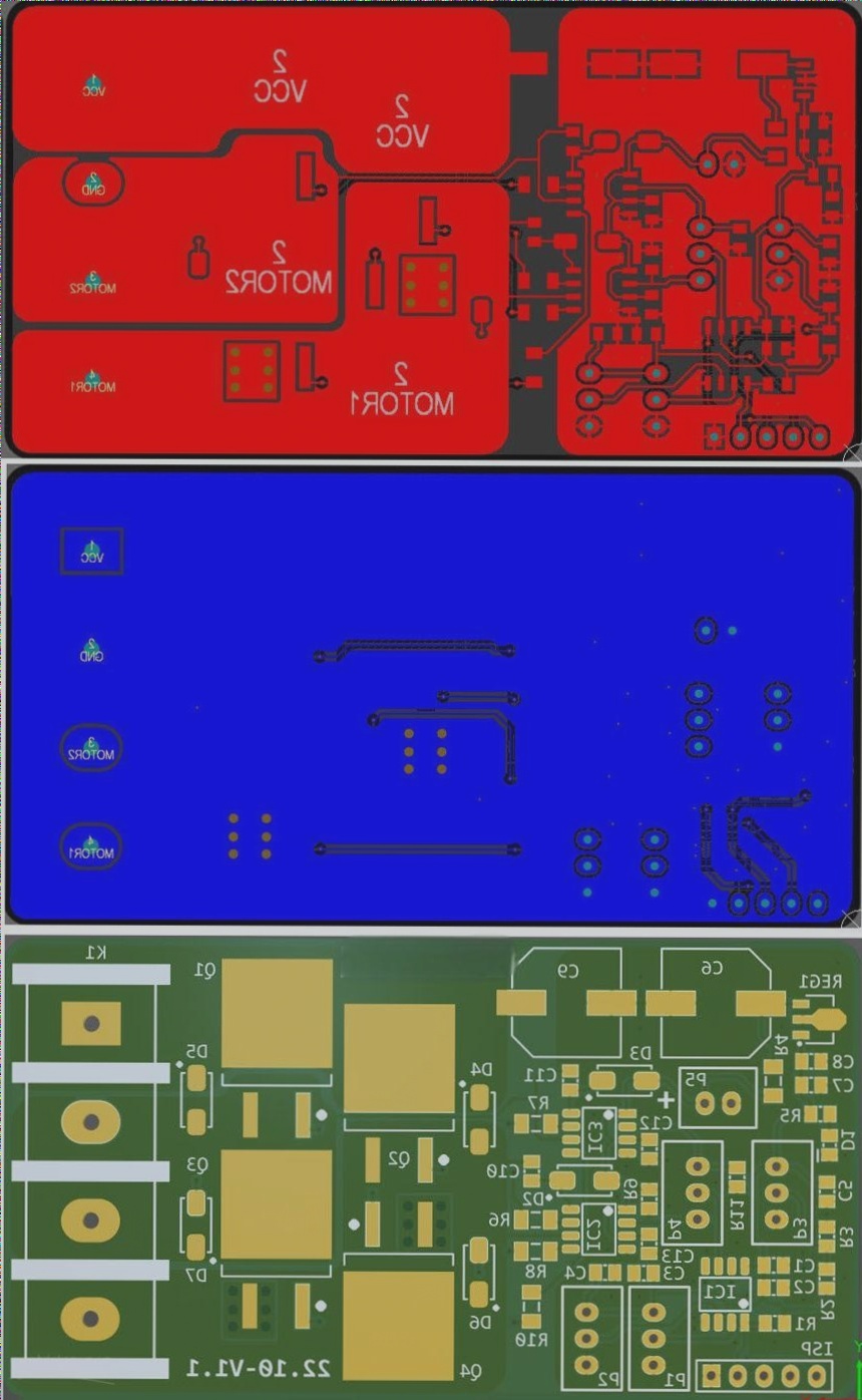
Figure 4
Assembly drawings of the PCB board
Code
The code for this project was developed using the Arduino IDE and the MicroCore hardware package for ATTiny13 [5]. To compile the code for ATTiny13, ensure you have installed this package. A compiled HEX file [6] is provided for your convenience. You will need an AVR ISP programmer like USBasp to burn the HEX file onto the ATTiny13. Set the fuse bits for a 9.6 MHz internal clock with no clock division (division = 1). The ISP programming pinout is shown in Figure 5.
#include <util/delay.h>
// Clock at 9.6MHz
#define F_CPU 9600000
const int PWMPin = 1;
analog_pin_t FVOLPin = A3;
analog_pin_t RVOLPin = A