A. Requirements and Precautions for Using Common Tools in PCBA Processing
-
Cutting Pliers
Usage Requirements:
- The cutting edge of the pliers should be sharp, especially at the foot-cutting station. Regular inspections are necessary to ensure optimal performance.
- When twisting component leads, the front end of the pliers should be intentionally dulled to prevent damage to delicate components.
Precautions:
- Always inspect the cutting edge for wear and damage before use.
- Avoid using cutting pliers beyond their intended purpose to prevent tool damage or component breakage.
-
Electric Soldering Iron
Temperature Control:
- A constant temperature soldering iron should maintain a stable temperature of 360°C ± 20°C for effective soldering without damaging components or the PCB.
Precautions:
- Always verify the temperature setting before use to avoid overheating sensitive parts.
- Regularly clean the soldering iron tip for efficient heat transfer and to prevent oxidation.
General Maintenance:
- Replace the soldering iron tip when signs of wear are evident.
Nominal Power 60W (with ESD Protection) – Soldering and Screw Assembly Techniques
1. Soldering Techniques:
- Soldering Iron Selection: A constant temperature soldering iron with a power rating of 60W or less is ideal for tin inspection and fixed tinning.
- Hot Air for IC Rework: Use hot air for IC rework, ensuring careful attention to prevent overheating and damage to surrounding components.
2. Wind and Electric Screwdrivers:
- Wind Screwdriver: Suited for screw assembly requiring medium torque.
- Electric Screwdriver: Ideal for precise, low-torque control under 4 Kg·cm.
Usage Recommendations:
- Stop the electric screwdriver once the screw is seated to avoid over-tightening.
- Proper alignment is crucial for the torque of self-tapping screws to ensure a secure fit.
Common Methods for Analyzing PCBA Failures
PCBA and Failure Phenomena:
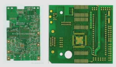
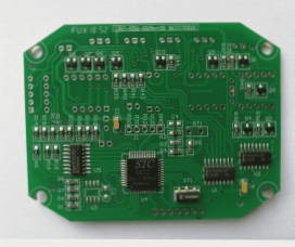
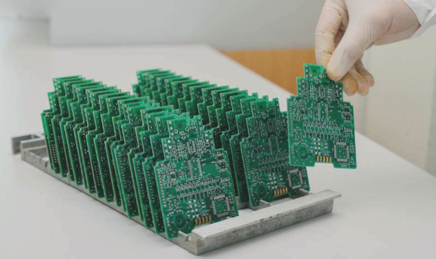
Modern electronic assembly emphasizes PCBA (Printed Circuit Board Assembly) as a core component. Failures can be manufacturing or user-induced, affecting overall reliability.
Purpose of Failure Analysis:
- Improve assembly reliability by analyzing manufacturing and user-induced failures.
PCB Failure Analysis: Enhancing Product Reliability
- Failure analysis aims to identify the root cause of failures, address issues in design and manufacturing, and propose preventive measures.
- Insights from failure analysis help refine processes, optimize manufacturing, and improve product usability for higher reliability.
PCBA Failure Rate Insights
- Component Failure Rate Curve: Aging components before deployment reduces failure rates during the product’s lifespan.
- Component Supply Life Curve: Lifespan of components affects system reliability in user environments.
- PCBA Assembly Failure Rate Curve: Solder joint quality is crucial for PCBA lifespan and system reliability.
Instantaneous Failure Rate Curve
- Premature Aging Zone: Early-life failures from manufacturing defects.
- Product Service Zone: Stable failure rate during normal operation.
- Aging Zone: Increased failure rate due to component wear-out and material degradation over time.
Principles and Methods of PCBA Failure Analysis
- Levels of Failure Analysis: Inspection of PCBA integrity and root cause identification.
- Principles of Failure Analysis: On-site data, retesting, process analysis, environmental factors, and knowledge accumulation are key.
- Methods of Failure Analysis: Utilize visual inspection, X-ray analysis, thermal imaging, and electrical testing for accurate issue identification.
If you have any inquiries about PCB or PCBA, don’t hesitate to contact me at info@wellcircuits.com.