Surface Mount Technology (SMT) Revolutionizing Electronic Assembly
In recent years, Surface Mount Technology (SMT) has emerged as a game-changer, replacing traditional through-hole insertion methods in electronic equipment development. This revolutionary advancement aims to boost product reliability, performance, and cost-efficiency, impacting both consumer and military electronic products.
Introduction to SMT and PCB Components
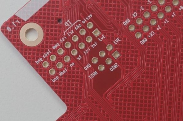
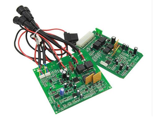
SMT is an electronic assembly technique where components are directly mounted onto a Printed Circuit Board (PCB) surface without the need for insertion holes. Solder is used to establish both mechanical and electrical connections between components and the PCB. SMT-based electronic products typically comprise printed circuit boards and surface mount components. Printed Wire Boards (PWBs) are single-sided or multilayer materials containing conductive traces and pads. Surface mount components fall into two categories: surface mount passive components and surface mount devices (SMDs). Passive components include resistors, capacitors, and inductors, while SMDs encompass active components like Small Outline Packages (SOP) and Ball Grid Arrays (BGA).
Surface Mount Technology Process Overview
The Surface Mount Technology (SMT) process involves primary steps: printing, component placement, and reflow soldering. These steps are crucial for all products and are followed by auxiliary processes like dispensing and optical-assisted automatic inspection, depending on product characteristics and user requirements.
- Printing Process: This step accurately applies solder paste to the PCB using a stencil and printing equipment. Solder paste, stencil, and the printing system are key elements in this process, ensuring proper electrical and mechanical connections.
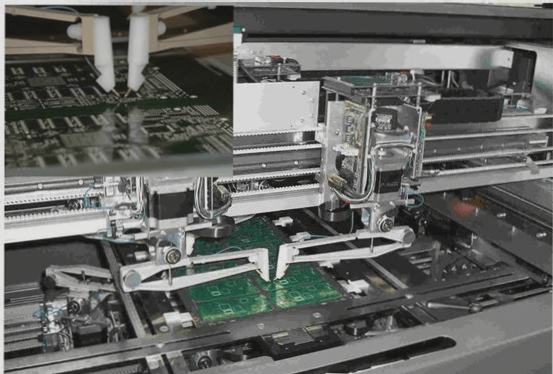
- Placement Process: This step focuses on the accurate and rapid attachment of components to the PCB. The placement machine’s precision and technologies like motion control, high-speed feeding mechanisms, and machine vision play vital roles in component alignment.
The Importance of Reflow Soldering in PCB Assembly
- Reflow soldering is a crucial process in PCB assembly, ensuring reliable mechanical and electrical connections.
- The reflow oven, with its heating, cooling, flux management, and inert gas protection systems, plays a key role in achieving optimal soldering.
- Efficient heating, precise temperature control, and proper cooling are essential for high-quality solder joints and preventing PCB warping.
- Proper flux management is necessary to prevent contamination and ensure a clean assembly environment.
- Using inert gas like nitrogen can minimize oxidation and improve soldering activity, especially for delicate components.
Auxiliary Processes for Enhanced PCB Assembly
- Dispensing special glue helps protect components during reflow soldering, preventing detachment or degradation.
- Optical-assisted automatic inspection tools ensure accurate solder paste application, component placement, and solder joint quality.
- Processes like dispensing and optical inspection support proactive and post-assembly inspections for high-quality PCBs.
Principles and Temperature Curve of Reflow Soldering
Reflow soldering follows a specific temperature curve to achieve optimal soldering results:
- Preheating Zone: Evaporation of solvent and gas, activation of flux.
- Soaking Zone: Full preheating of PCB and components to prevent thermal shock.
- Reflow Zone: Rapid temperature rise to melt solder paste and bond components.
- Cooling Zone: Solidification of solder to complete the reflow process.
The temperature curve is crucial for quality solder joints, with specific temperature ranges for each phase of the process.
Key Temperature Zones:
- Preheating Zone: Room temperature to 120°C.
- Soaking Zone: 120°C to 170°C.
- Reflow Zone: 170°C to 230°C.
- Cooling Zone: Approximately 210°C to 100°C.
Controlled heating rates and peak temperatures are essential for preventing solder joint defects and ensuring soldering quality.
The Importance of Reflow Soldering Temperature Profile in PCB Assembly
The reflow soldering temperature profile plays a crucial role in determining the quality and reliability of PCB assembly. Factors such as solder paste specifications, PCB material, component size, and oven settings all contribute to achieving the desired soldering results.
Key Factors Influencing Reflow Soldering Temperature Profile
- Solder paste specifications
- PCB material and thickness
- Component size and density
- Type of components (e.g., BGAs or CSPs)
- Equipment factors (oven length, heating source material)
Understanding the Reflow Process
In a typical reflow oven, different temperature zones are crucial for successful soldering:
- Heating zone
- Soaking zone
- Rapid heating zone
- Reflow zone
- Cooling zone
Optimizing Reflow Soldering Parameters
Specific parameters such as temperature ramp rates, dwell times, and cooling rates are essential for achieving a proper reflow profile. Maintaining the right temperature curve is critical for ensuring the quality and performance of the soldered components.
Importance of Regular Monitoring
Regular checks of the reflow oven and comparison of the actual temperature curve with the standard profile are necessary to uphold consistent soldering quality and electrical performance.
Advancements in Surface Mount Technology
Surface mount technology has revolutionized electronic assembly, enhancing soldering quality and product reliability. By adhering to proper reflow soldering practices and monitoring temperature profiles, manufacturers can ensure that mounted components meet stringent quality standards.