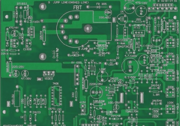
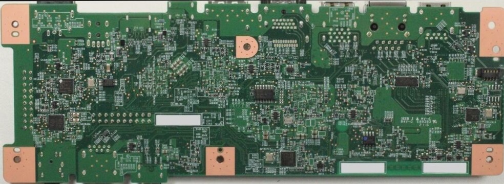
1. Establishing a physical border
The closed physical frame serves as a fundamental platform for component layout and routing, also acting as a constraint for automated placement. Without it, components derived from the schematic may be disoriented. Accuracy is vital in this step, as installation issues can lead to complications down the line. Additionally, it is advisable to incorporate arcs at the corners. This not only prevents sharp edges from causing injuries but also mitigates stress impacts. I previously experienced a situation where one of my products consistently had the PCB board of the face shell damaged during transport, but switching to arcs resolved the issue.
2. Introducing components and networks
Placing components and defining networks within the established frame should be straightforward; however, challenges frequently arise. It is essential to address errors methodically based on the prompts provided. Neglecting this can lead to increased effort later on. Common issues include difficulties in locating the component package, network problems, and the presence of unused components or pins. These challenges can usually be resolved quickly through careful comparison.

3. Component Layout
The arrangement and wiring of components significantly influence the product’s lifespan, stability, and electromagnetic compatibility, thus warranting careful consideration. Generally, the following principles should be adhered to:
(1) Placement Order
Begin by positioning structural components in fixed locations, such as power sockets, indicator lights, switches, and connectors. Once these components are in place, use the software’s LOCK function to prevent accidental movement. Next, position special and larger components like heating elements, transformers, and ICs. Finally, place the smaller devices.
(2) Attention to Heat Dissipation
Heat dissipation is critical in component layout. For high-power circuits, heating elements such as power tubes and transformers should be positioned close to the edges to facilitate cooling. Avoid clustering components, and ensure that high-capacitance components are not placed too closely to prevent premature electrolyte aging.
4. PCB Wiring Principles
Routing knowledge is advanced, with each designer having their own experience, yet some common principles exist.
◆ High-frequency digital circuit traces should be thinner and shorter.
◆ Ensure adequate isolation between high-current, high-voltage, and small signals; the isolation distance is related to the required withstand voltage. Typically, a distance of 2mm is sufficient for 2kV; this should be increased proportionately for higher voltages (e.g., for 3kV, maintain a distance above 3.5mm). Slots may be added on the PCB to prevent creepage between high and low voltage areas.
◆ When connecting two panels, ensure that wires on both sides are perpendicular, angled, or curved to minimize parallel routing, thereby reducing parasitic coupling. Avoid using printed wires as circuit inputs and outputs; if unavoidable, place a grounding wire between them to mitigate feedback.
◆ Aim for corner angles greater than 90 degrees; minimize sharp corners below this threshold.
◆ For the same address or data line, ensure trace lengths are similar; significant differences necessitate manual bends for compensation.
◆ Traces should predominantly be on the soldering surface, especially for PCBs using through-hole technology.
◆ Minimize the use of vias and jumpers.
◆ Pads on single-layer boards should be large, and connections must be thick; use teardrops where appropriate. The quality of single-layer manufacturers is often variable, which can lead to soldering and rework issues.
◆ Large copper areas should have a grid pattern to prevent bubbling and board warping during wave soldering, but consider the flow direction and size of the GND—avoid simply filling with copper foil.
◆ Components and wiring should not be positioned too close to the edges; single-sided boards are usually paper-based and susceptible to damage under stress.
◆ Production, debugging, and maintenance convenience should be a priority.
Ground issues are crucial for analog circuits. Ground noise can be unpredictable but leads to significant complications once present. In power amplifier circuits, even minimal ground noise can substantially affect sound quality due to amplification. In high-precision A/D conversion circuits, high-frequency noise on the ground can introduce temperature drift, impacting amplifier performance. Adding decoupling capacitors at the corners of the board—connecting one pin to the board ground and the other to a mounting hole (linked to the housing via screws)—can stabilize the amplifier and A/D performance.
Moreover, electromagnetic compatibility has gained importance with the rise of eco-friendly products. Typically, electromagnetic signals originate from three sources: signal sources, radiation, and transmission lines. Crystal oscillators are common high-frequency signal sources, with each harmonic exhibiting significantly higher energy levels than average. Effective strategies include controlling signal amplitude, grounding the crystal housing, shielding interference, and utilizing specialized filter circuits.
Special attention should be given to serpentine traces, as their functions vary with application. They are used for clock signals on motherboards, such as PCIClk and AGP-Clk, serving two primary purposes: 1. Impedance matching, and 2. Filtering inductance. For critical signals like HUBLink in the INTELHUB architecture, with 13 channels operating at up to 233MHz, strict length equality is vital to avoid timing issues. Serpentine routing is often the only viable solution.
In general, the spacing of serpentine traces should be at least twice the trace width; when used on standard PCBs, they can also serve as inductive coils for radio antennas.


