The operation of electronic equipment leads to the generation of heat, which in turn causes a rapid increase in internal temperature. This temperature rise primarily stems from the power consumption devices within the circuit. Electronic devices exhibit varying degrees of power consumption, directly influencing the intensity of heat produced. Failure to dissipate this heat promptly can result in continued temperature elevation, leading to device malfunction and a decrease in electronic device reliability. Consequently, effective heat dissipation from the circuit board is crucial.
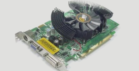
To address circuit board overheating, common solutions involve the installation of heat sinks or fans for cooling. However, these external additions not only incur additional costs but also prolong manufacturing time. Moreover, integrating fans introduces reliability concerns due to potential instability. Consequently, active cooling methods are preferred over passive ones in circuit board design. Here are several approaches to consider for circuit board heat dissipation:
1. Utilize the PCB board itself for heat dissipation.
2. Incorporate radiators and heat-conducting plates alongside high heat-generating devices.
3. Implement a rational wiring design to facilitate heat dissipation.
4. Position temperature-sensitive devices in cooler areas, avoiding direct placement above heat sources. Staggering multiple devices horizontally is advisable.
5. Optimize airflow paths during design to facilitate heat dissipation across the printed board.
6. Ensure even distribution of power across the PCB surface to prevent hotspots and maintain uniform temperature performance.
7. Place devices with the highest power consumption and heat generation in optimal positions for heat dissipation.
8. Arrange integrated circuits vertically or horizontally for equipment employing free convection air cooling.
9. Organize devices on the printed board based on their heat generation and dissipation capabilities. Place low-heat devices at the cooling airflow entrance and high-heat devices downstream.
10. Position high-power devices close to the board edge horizontally to shorten heat transfer paths. Vertically, place them near the top to minimize the impact on surrounding devices.
11. Minimize thermal resistance between high heat dissipation devices and the substrate. Use thermal conductive materials, such as thermally conductive silica gel, to enhance heat dissipation efficiency.
As a professional FPC soft board manufacturer, WellCircuits Limited is proud to have collaborated with many clients. We remain committed to assisting our new customers in any way possible. Please feel free to reach out to us with any inquiries.


