Empowering Electronic Reliability with ANSYS
Electronic equipment and systems are integral to modern society, from aircraft and trains to medical systems and manufacturing equipment. Ensuring high reliability in these systems is crucial as their complexity and importance continue to grow.
Advancements in Electronic Systems
The reliance on electronic systems is increasing with the progress of big data and artificial intelligence technologies. This escalation raises the stakes for ensuring reliability in electronic products.
ANSYS at DesignCon 2020
At DesignCon 2020, ANSYS showcased how they enable engineers to create highly reliable products. ANSYS, based near Pittsburgh, Pennsylvania, has a team of 4,000 experts specializing in various fields such as finite element analysis, computational fluid dynamics, and electronics.
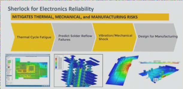
Integration of Sherlock for Enhanced Reliability Analysis
ANSYS’s acquisition of DfR Solutions, including Sherlock software, has strengthened their capabilities in semiconductor packaging, PCBA simulation, and electronic reliability analysis. This integration allows for comprehensive failure analysis early in the design phase, leading to significant time and cost savings during product development.
Value of ANSYS Sherlock Finite Element Analysis (FEA)
ANSYS Sherlock FEA empowers engineers to assess hardware reliability from the beginning of the design process. This tool enables designers to evaluate different architectures, geometries, and materials thoroughly, optimizing product outcomes across various conditions.
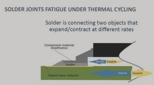
Anticipating Hardware Failures
Through physical failure principles, Sherlock and ANSYS help IC designers anticipate potential failures, such as cracks in low-K dielectric materials or solder joints in integrated circuits. By identifying these issues early, designers can take corrective actions promptly, avoiding costly redesign cycles.
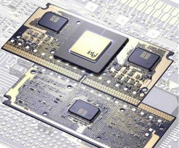
Recent Trends in Integrated Circuits
- Many integrated circuits now use lead-free solder bumps for connections, but variations in thermal expansion coefficients can strain these joints.
- Copper columns are becoming popular for their smaller spacing, although they may be more susceptible to failure under strain due to their rigidity.

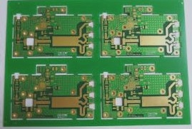
The Latest in PCB Technology and Simulation Solutions
- The use of micro-through hole technology in PCBs is on the rise due to space constraints in electronic devices.
- Stacking micropores up to four stories high has become common practice.
- Improper material selection and design geometry in micropores can lead to unexpected cracking and layering.
- Thermal-mechanical stress, moisture, and vibration can cause separation of micropores and layering of copper trace lines in electroplated through holes.
- Sherlock software analyzes stress conditions and predicts potential failures in interconnections within PCBs.
Even advanced tools like Sherlock need to be seamlessly integrated into a user-friendly design flow to maximize their value. By combining Sherlock with ANSYS Icepak and ANSYS Mechanical, engineers can achieve a “zero defect” design goal efficiently.
Enhancing Electronic Cooling Solutions with ANSYS Icepak
ANSYS Icepak offers robust cooling solutions for thermal and fluid flow analysis in various electronic components, from ICs to entire data centers. Its advanced features simulate laminar and turbulent flow, radiation, and convection, providing solutions to common electronic cooling challenges.
The Future of Connectivity: Ansys 5G Simulation Solution
The impending 5G technology revolution is set to transform industries and daily life with ultra-fast, ubiquitous connectivity. Ansys 5G Simulation equips engineers to overcome design complexities in devices, networks, and data centers, ensuring quality-of-service targets are met in the era of 5G connectivity.
Phased Array Design Process in ANSYS HFSS
The design process for phased arrays in ANSYS HFSS is a detailed and systematic procedure. ANSYS HFSS is a powerful 3D electromagnetic tool that specializes in designing and simulating a wide range of high-frequency electronic products, such as antennas, antenna arrays, RF and microwave components, resonators, filters, and other high-frequency electronic components.
When initiating the phased array design process in HFSS, it begins with creating a single unit prototype. This prototype allows for the optimization of antenna design parameters using the experimental design (DoE) method. Following this optimization, the entire array is synthesized to simulate and optimize its overall performance within ANSYS HFSS.
After the array synthesis, the next step involves modeling and simulating the installed antenna and its interaction with the surrounding environment. This is achieved by utilizing a hybrid solver in ANSYS HFSS, combining the SBR+ method with ray-tracing technology for accurate and efficient analysis.