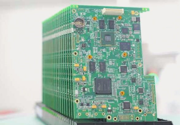
Restoring a circuit schematic diagram in a circuit board factory involves a systematic approach based on the layout of the PCB circuit board. Drawing on the experience of circuit board manufacturing, the identification and separation of the ground wire, power cord, and signal wire are crucial steps.
Taking the power circuit as an example, the negative end of the rectifier tube connected to the secondary of the power transformer serves as the positive pole of the power supply. Typically, a large-capacity filter capacitor is connected to the ground wire. The power line and ground wire can also be traced from the pin of the three-terminal voltage regulator.
In the wiring process, the circuit board factory employs specific strategies to prevent self-excitation and interference. The ground wire copper foil is typically set to the widest, with the power line copper foil following, and the signal wire copper foil being the narrowest. In electronic products featuring both analog and digital circuits, the printed board often separates the respective ground wires, forming an independent ground connection network.
For effective identification, the printed board may be marked with component serial numbers (e.g., VD870, R330, C466). These serial numbers follow specific rules, with the first Arabic numeral after the English letter belonging to the same functional unit. Properly distinguishing components within the same functional unit is fundamental to drawing layout.
Various circuit board manufacturing methods can be applied to restore the circuit schematic diagram. If component numbers are absent, assigning numbers for ease of circuit analysis and proofreading is recommended. To optimize the layout, circuit board manufacturers concentrate components of the same functional unit in a relatively compact manner, facilitating the identification of other components within the unit.
The shortest path for the copper foil is a key consideration, prompting circuit board manufacturers to design the components of the printed board in a concentrated manner. Once the core device of a unit is identified, other components of the same functional unit can be located by following the layout. To prevent excessive connections and ensure clarity, terminal marks and grounding symbols are widely used for power supply and ground wires.
In cases where numerous components are involved, drawing separate circuits for each unit and then combining them can enhance clarity and organization in the circuit schematic diagram.

