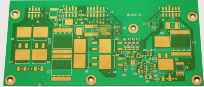
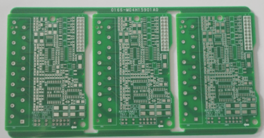
1. The term “circuit board gold finger” refers to a series of uniformly spaced square pads that are exposed in copper and gold plating.
2. These are primarily utilized as electrical connection points for components such as board cards, LCD connections, motherboards, and chassis.
3. This design typically features a copper foil with a nickel-plated layer, which is then coated with a thin layer of gold.
1. The definition and function of the gold finger core board in a PCB circuit board: Golden Finger: (GoldFinger or EdgeConnector) This refers to inserting one end of the PCB circuit board into a connector slot, utilizing the connector pins as the interface to connect the circuit board to external devices. The pad or copper layer contacts the pins at specific positions to facilitate conduction. These pads are plated with nickel and gold, earning the term “gold finger” due to their finger-like appearance. Gold is chosen for its excellent conductivity and resistance to oxidation. However, due to the high cost of gold, it is used only for selective gilding, such as on gold fingers.
2. Secondly, the classification and identifying characteristics of the gold finger core board in circuit boards: The gold finger classifications are as follows: 1. Conventional gold finger (flush finger); 2. Segmented golden fingers (intermittent fingers); 3. Long and short golden fingers (uneven fingers). Gold finger circuit boards come in various lengths: 1. Conventional gold fingers (flush fingers) feature rectangular pads of uniform length and width arranged neatly along the board’s edge. The image below illustrates network cards, graphics cards, and similar devices, which typically have numerous gold fingers, whereas smaller boards may have fewer. 2. Segmented golden fingers (intermittent fingers) have rectangular pads of varying lengths on the board’s edge, with the front section disconnected. 3. Long and short golden fingers (uneven fingers) also consist of rectangular pads of different lengths along the edge of the board.
3. PCB circuit board gold finger identification features include: no character frames or markings, with standard solder mask openings. Most shapes contain grooves. The gold finger often extends partially from the board’s edge or is positioned close to it, with some boards featuring gold fingers at both ends. While standard gold fingers are typically on both sides, some PCB circuit boards only have gold fingers on one side. Additionally, certain circuit boards may showcase a single, wide gold finger.
4. Home entertainment host terminal products utilizing the RK3399 platform demonstrate technological leadership across multiple display interfaces, GPU capabilities, audio and video decoding, interconnection with various terminals, and enhanced human-computer interaction. The VR head-mounted display device based on the RK3399 platform can achieve a delay of under 20ms with optimized algorithms, alongside a refresh rate of 90Hz and 4K UHD decoding, enabling ultra-high-definition H.265/H.264 video resolution. By employing the Type C or HDMI+USB interface, an external VR headset delivers an immersive virtual reality experience.
5. Analysts assert that the chip, positioned at the industry’s forefront, has consistently held the mission of innovation and leadership. The Rockchip RK3399’s open interface and open-source system not only facilitate terminal equipment manufacturers in leveraging a single chip for a comprehensive global product lineup but also enable rapid product development, cost efficiency, and technical application. Its open-source framework meets terminal manufacturers’ needs for product customization and differentiation, effectively addressing industry chain challenges and holding significant value for the advancement of global intelligent hardware.