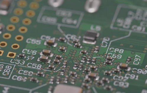
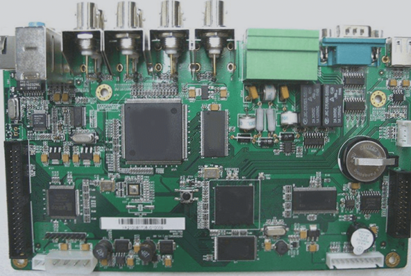
1. Today’s mass-produced electronic hardware is predominantly manufactured using surface mount technology (SMT).
2. There are compelling reasons why SMT PCB boards significantly expedite PCB production while offering numerous other advantages.
1. The component mounting offset mainly refers to the positional deviation in X-Y after components are mounted on the PCB board. The causes are as follows:
1) PCB board reasons:
a. Excessive warpage of the PCB beyond equipment tolerances; maximum up warping is 1.2mm and maximum down warping is 0.5mm.
b. Inconsistent height of support pins leading to uneven PCB support.
c. Poor flatness of the workbench support platform.
d. Low wiring accuracy and consistency of the circuit board, particularly noticeable between different batches.
2) Insufficient suction air pressure from the mounting nozzle, which should be above 400mmHG during removal and mounting.
3) Abnormal blowing pressure during mounting.
4) Abnormal or misaligned coating of adhesive and solder paste. This causes component drift during mounting or soldering, and discrepancies in component positions when the worktable moves at high speed post-mounting due to inaccurate coating positions and resulting tension.
5) Incorrect program data settings.
6) Poor positioning of the base plate.
7) Non-smooth movement and slow rise of the mounting nozzle.
8) Loose coupling between power and transmission parts of the X-Y worktable.
9) Improper installation of the mounting head nozzle.
10) Mismatch between the blowing time sequence and the descending time sequence of the mounting head.
11) Poor initial data settings for suction nozzle center data and the optical identification system camera.
2. Surface mount technology involves five key steps:
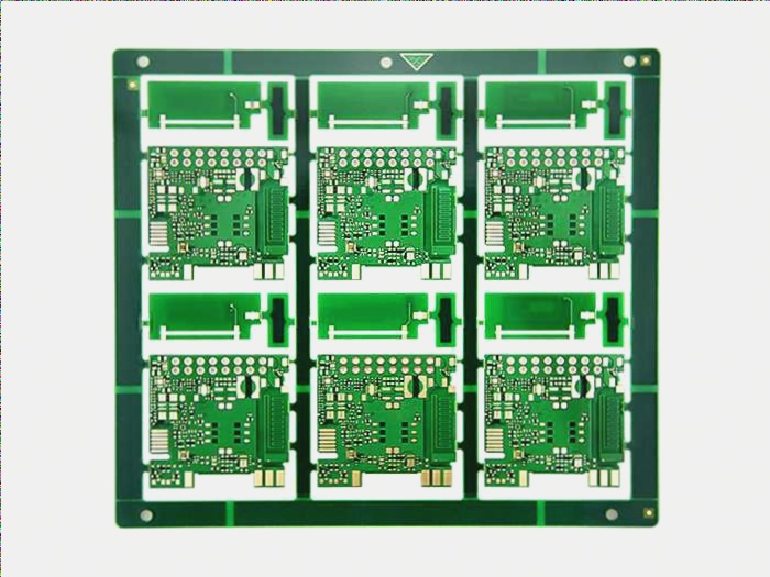
1) PCB production – actual manufacturing of PCBs with solder points.
2) Deposition of solder on pads to secure components to the board.
3) Machine-assisted placement of components precisely onto solder joints.
4) Baking of PCB to solidify flux.
5) Inspection of completed components.
3. Differences that distinguish SMT from through-hole technology include:
Surface mount technology resolves space constraints often encountered in through-hole assembly. SMT offers design flexibility, enabling PCB designers to freely create dedicated circuits. Smaller component sizes allow more components on a single board, reducing the need for multiple boards. SMT components are lead-free, with shorter lead lengths reducing signal delays and package noise. Higher component density per unit area is achievable by mounting components on both sides. SMT is suited for mass production, thereby reducing costs and enhancing circuit speed. The surface tension of molten solder aligns components with pads, correcting minor placement errors automatically. SMT proves more stable against vibrations. SMT parts are generally more cost-effective than similar through-hole counterparts.
However, SMT has inherent limitations. It may not be reliable for components under significant mechanical stress. Heat-generating or high-electrical-load components can’t be installed with SMT due to solder melting risks at high temperatures. Therefore, through-hole installation remains preferable in cases involving special mechanical, electrical, or thermal requirements. Similarly, SMT is less suitable for prototyping where component addition or replacement may be necessary, and high-density PCBs can pose support challenges.