Short circuit issues on PCB circuit boards are a common challenge in the production process. Generally, there are two main types of short circuits. The first occurs when the PCB has reached the end of its service life. The second type arises when the PCB’s production inspection is insufficient. Even minor errors during production can lead to component failure, which, in turn, can damage the entire PCB and result in scrap. Therefore, it is crucial to conduct thorough inspections and quality control throughout the production process. So, what are the common types of PCB circuit board short circuits? What key factors should be considered when inspecting short circuits on a PCB?
**1. Common types of circuit board short circuits:**
1. Short circuits can be categorized by function, including: soldering short circuits (e.g., solder bridges), PCB circuit board short circuits (such as residual copper, hole misalignment, etc.), internal micro short circuits within the board, component short circuits, assembly short circuits, ESD/EOS failures, and electrical/chemical short circuits (e.g., chemical residues, electrochemical migration), along with other causes of short circuits.

2. Short circuits can be categorized into line-to-line short circuits, line-to-layer short circuits, and face-to-face (layer-to-layer) short circuits, based on the wiring characteristics.
Next, there are several important considerations when inspecting a circuit board for short circuits:
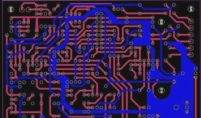
1. When opening the PCB design in the computer, the short-circuit network will light up, and it’s easiest to identify potential short circuits by observing areas that are close together. Special attention should be paid to short circuits within the ICs.
2. If performing manual soldering, it’s important to develop good habits:
(1) Visually inspect the PCB before soldering to check for any potential short circuits, especially in key circuits like power and ground, using a multimeter.
(2) Avoid dropping soldering iron tips onto the board. If solder splashes onto the solder pads of a chip (especially on surface-mount devices), it can be difficult to detect.
(3) After soldering each chip, use a multimeter to check for any short circuits between the power supply and ground.
3. If a short circuit is detected, remove the board and cut the traces (this method is especially effective for single or double-layer boards). After cutting the traces, power up individual sections of the circuit and gradually isolate the faulty block.
4. Use a short-circuit location analyzer. Common options include: the Singapore PROTEQCB2000 short-circuit tracker, the Hong Kong Smart Technology QT50 short-circuit tracker, and the UK POLARtone Ohm950 multilayer board short-circuit detector.
5. For the current-checking method: apply a low voltage and high current, typically under 5V and 3-5A. The heated area will likely indicate a short circuit. However, this method carries a minimal risk and is generally not commonly used.
6. For BGA chips, where the solder joints are hidden beneath the chip coverage and the board is a multilayer PCB (over 4 layers), it is advisable to split the power supply for each chip in the design. Use magnetic beads or 0-ohm resistors for the connections. When shorting the power supply and ground, disconnect the magnetic beads to help locate the fault. Given the complexity of BGA soldering, if machine soldering is not available, special care must be taken to prevent shorts between the adjacent power and ground solder balls.
7. Exercise caution when soldering small capacitors, especially power supply filter capacitors (such as 103 or 104 types), as they are numerous and can easily cause shorts between power and ground. Occasionally, faulty capacitors themselves can cause short circuits. Therefore, the best practice is to test the capacitors before soldering them.
If you have any PCB manufacturing needs, please do not hesitate to contact me.Contact me


