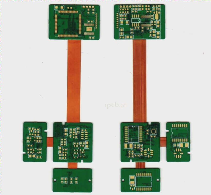
1. FPC Electroplating on Flexible Circuit Boards
(1) Pre-treatment for FPC Electroplating. The copper conductor surface exposed during the FPC coating process may become contaminated with adhesives or ink, and high-temperature processes can lead to oxidation and discoloration. To achieve a dense coating with strong adhesion, it is essential to remove any contaminants and oxide layers from the conductor’s surface, ensuring it is clean. However, some of these contaminants bond very tightly to the copper conductors and cannot be completely removed with mild cleaning agents. As a result, most are treated using alkaline abrasives of sufficient strength along with brushing. The covering adhesives, primarily epoxy resins, exhibit poor alkali resistance, which can reduce bonding strength. Although this may not be visually apparent, during the FPC electroplating process, the plating solution can infiltrate from the edges of the cover layer, potentially causing severe peeling. During final soldering, the solder can also penetrate beneath the cover layer. Thus, the pre-treatment cleaning process significantly impacts the fundamental characteristics of the flexible printed circuit board (FPC), and careful attention must be paid to processing conditions.
(2) Thickness of FPC Electroplating. The deposition rate of the electroplated metal during the electroplating process is directly influenced by the electric field intensity. This electric field intensity varies based on the circuit pattern’s shape and the spatial relationship between the electrodes.
Generally, the thinner the wire line width, the sharper the terminal at the endpoint. As the distance to the electrode decreases, the electric field strength increases, resulting in a thicker coating at that location. In applications involving flexible printed boards, it is common to encounter situations where the widths of various wires within the same circuit differ significantly. This disparity can lead to uneven plating thickness. To mitigate this issue, a shunt cathode pattern can be added around the circuit to absorb the uneven current distribution during the electroplating process, thereby maximizing the uniformity of the coating thickness across all areas. Thus, careful attention must be given to the electrode structure. A compromise is proposed here: stringent standards are set for components requiring high coating thickness uniformity, while other areas can have more relaxed standards. For instance, lead-tin plating for fusion welding has high requirements, as does gold plating for metal wire overlap (welding). In contrast, the plating thickness requirements for lead-tin plating used for general anti-corrosion applications can be more lenient.
(3) Stains and Contaminants in FPC Electroplating
Initially, the state of the electroplated layer appears satisfactory, particularly regarding its appearance. However, shortly thereafter, stains, dirt, discoloration, and other issues can manifest on the surface. Although these problems may not be detected during factory inspections, they often become apparent during the user’s acceptance testing. This phenomenon is typically caused by insufficient rinsing, leaving residual plating solution on the surface of the plating layer, which can lead to slow chemical reactions over time. Notably, flexible printed boards tend to be less flat due to their flexibility, causing various solutions to “accumulate” in recesses, leading to reactions that change color in those areas. To prevent this occurrence, thorough rinsing is essential, along with complete drying. A high-temperature thermal aging test can be employed to verify the adequacy of the rinsing process.
FPC Plating
2. Electroless Plating on Flexible Circuit Boards
When the line conductors intended for electroplating are isolated and cannot serve as electrodes, electroless plating becomes the only viable option. The plating solutions used in electroless plating typically exhibit strong chemical activity, with electroless gold plating being a notable example. The electroless gold plating solution is an alkaline aqueous solution with a very high pH. When employing this electroplating process, there is a tendency for the plating solution to penetrate beneath the covering layer, especially if the quality management during the covering film lamination process is lax and the bonding strength is insufficient.
Given the characteristics of the plating solution, the electroless plating of the displacement reaction is particularly prone to issues of solution penetration under the covering layer, making it challenging to achieve ideal plating conditions through this process.
Three, Flexible Circuit Board FPC Hot Air Leveling
Hot air leveling was initially developed for rigid printed board PCB coating with lead and tin. Due to its simplicity, this technology has also been adapted for flexible printed boards (FPC). The hot air leveling process involves immersing the board directly and vertically into a molten lead-tin bath and then using hot air to blow off the excess solder. This method presents significant challenges for flexible printed boards (FPC). If the flexible printed board cannot be immersed in the solder without precautions, it must be clamped between screens made of titanium steel before immersion. Additionally, the surface of the flexible printed board must be cleaned and coated with flux beforehand.
The harsh conditions inherent in the hot air leveling process can lead to solder penetration from the edge of the cover layer into the underlying area. This issue is more likely to occur when the bonding strength between the cover layer and the copper foil surface is low. Since polyimide film readily absorbs moisture, this moisture can cause bubbling or even peeling of the cover layer due to rapid heat evaporation during the hot air leveling process. Therefore, it is essential to ensure that the FPC is thoroughly dried and moisture-proofed prior to undergoing the hot air leveling process.
If you have any PCB manufacturing needs, please do not hesitate to contact me.Contact me