The Art of Making Cute and Vivid Printed Circuit Board Ornaments
Have you ever thought of turning a printed circuit board into a fashionable accessory like a necklace or pendant? It’s not just for electronic enthusiasts anymore! These circuit boards can be transformed into adorable shapes like a fox, complete with solar charging capabilities and LED eyes emitting a warm amber glow.
Materials Needed for the Project:
- Temperature-adjusting electric soldering iron
- Solder
- Sharp-nosed pliers
- Crocodile clips for holding components
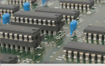
Components Used in the Circuit Diagram:
- C2-47uF Ceramic Capacitor (Blue-large)
- C3-10uF Chip Capacitor (Blue-small)
- C4-0.1uF Time Scale Capacitor (Brown)
- U2-MCP6542 Master IC
- SC1 to SC6-BPW34 ($0.4135) Photodiode
- R5-330 Ohmic Resistor (Orange band)
- R1/R2/R3/R4-10M Resistor (Brown and black tape)
- D1 and D2-Amber LED
- Switch-Single Pole Double Throw Switch
- C1-0.033uF (Black)
Assembling the Components:
Start by soldering the capacitors in the correct positions. Pay attention to the numbers and markings on the components to ensure proper placement. When soldering resistors, remember they have no polarity, and begin with resistor R5 for this project.
Soldering Tips:
For comfort, components are soldered on the front of the circuit board. When soldering delicate parts like the chip, discharge any static electricity by touching a metal object first. Take note of the chip’s orientation for proper placement.
Powering Your Fox Ornament:
By soldering a supercapacitor correctly, you can make your fox ornament run for over 3 hours. The positive and negative terminals are clearly marked for easy assembly.
Switch Soldering Tips
When soldering a switch, it’s important to note that there is no distinction between positive and negative electrodes.
Be cautious as the switch is typically made of ordinary plastic, which can easily melt and damage components if touched by the soldering iron.
LED Soldering Guide
When soldering LEDs, remember that the long pin is the positive pole, and the short pin is the negative pole.
Final Checks Before Operation
Once all soldering is complete, ensure everything is in place for your device to function properly.
Double-check your work before powering up your project.