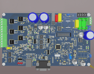
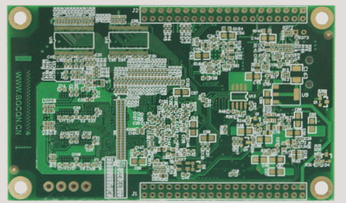
To design printed circuit boards, a variety of tools are available, including the open-source software “KiCAD” and numerous online services. Among open-source hardware enthusiasts, “EAGLE” by CadSoft is the most popular choice. In this article, you will explore how to utilize EAGLE for basic printed circuit board design, focusing on the essential core of an ATmega microcontroller board.
**Parts List**
▪ Resistor, 10K 1/8W
▪ Electrolytic capacitor, 47μf (2)
▪ Resistor, 1K 1/8W
▪ Momentary push button switch
▪ Ceramic oscillator, 16MHz
▪ ATmega328P microcontroller IC
▪ IC socket, 28 pins (optional)
▪ Diode, 4005
▪ Low-Dropout Linear Regulator (LDO), L4931
▪ Power socket
▪ 1×6 pin header
▪ Ceramic capacitor, 0.1μf (2)
**Tool List**
▪ A Windows, Mac, or Linux computer with internet access
▪ Cadsoft EAGLE stand-alone PCB design software
▪ RBBB EAGLE parts database
*Note: Although the parts list from RBBB is provided above, you don’t need to have all the components on hand; you can follow the design instructions below.*
**Using EAGLE**

EAGLE is a comprehensive software package that integrates multiple programs, each serving a specific design function. This discussion will concentrate on the “Schematic Editor” and “Board Editor,” while other modules include the Autorouter, Component Editor, CAM processing software (CAM Processor, used for generating machining files), and an interface for programming user-defined language programs (User Language Programs).
We can choose components from the component library, with each component represented by two types of icons, one for the circuit schematic and the other for the circuit board. Since most components originate from different libraries (packages), EAGLE’s component library enables different packages to link to the same component icon. To streamline the process, we have created an RBBB database containing the components necessary for this design. Once you’re familiar with the design process, the SparkFun database will serve as an excellent resource to expand your knowledge.
**EAGLE Workflow**
I. Design and Material Search: Identify parts, review specifications, download necessary files, and create blueprints.
II. Circuit Schematic Design: Connect various components using signal wires.
III. Circuit Rule Check (ErC): Utilize artificial intelligence (AI helper) to identify errors in the circuit.
IV. Circuit Board Design: Position the designed components on the circuit board and create physical connections.
V. Design Rule Check (DrC): Use AI to verify design errors.
VI. Generate Gerber and Drill Files: Use CAM processing software to create machining files.
1. **Getting Started**
First, download the EAGLE Light Edition from the Cadsoftusa.com website and acquire the RBBB component database from moderndevice.com/downloads. Place the package in the lbr database within the EAGLE program.
EAGLE distinguishes layers with different functions in CAD drawings using color. In the “Circuit Schematic Editing” window, the component icon appears in the “Symbols layer,” while its label resides in either the “Names layer” or “Values layer.” The network connections (Net) are found in the “Net layer.” You can show or hide these layers via the View Menu.
**Tip:** Regularly check your toolbar to ensure you are drawing on the correct layer.
1.1 Open the schematic editor and navigate to “File” – “New” – “Schematic.” A warning message will appear stating, “No forward/backward annotation will be performed.” This is because typically, the schematic diagram and board editor are opened simultaneously and synchronized; the message indicates that the PCB file has not yet been opened.
1.2 Select the “Add” tool and position the Frame component from the RBBB component database onto the workspace. While this step is optional, it simplifies the process of drawing the circuit schematic without constant adjustments to the screen size.
2. **Power Circuit**
These five components manage the reception of DC power input and output a noise-free 5V power supply. The central icon represents a voltage regulator. Key specifications for the voltage regulator include output voltage, maximum output current, and dropout voltage (the minimum difference between input and output potential). The L4931 voltage regulator has a minimal dropout voltage of only 0.4V, making it reliable for outputting 5V from a 6V input (such as from four AA batteries). It can supply up to 250mA, which is ample for most microcontroller applications.
**Rules of Thumb**
– A small dot signifies that two intersecting signal lines are connected; no dot indicates they merely overlap.
– Utilize the Grid tool, setting its size to 0.1 inch (100 mil), as a common mistake is assuming two lines intersect when they do not.
– Each line (network connection or signal line) has an independent name. Even if not adjacent, all signal lines sharing the same name will be automatically connected, simplifying complex designs.
– Each component should have a clear name and value. Adjust the labels to ensure clarity and legibility; use the Smash tool to separate labels from components and reposition them as needed.
– Drawing a schematic is akin to communicating with circuit components. Consider whether you’ve provided all the necessary functions.
2.1 Use the “Add” tool to select RBBB – Regulator and place the Regulator component in the upper left quadrant of the screen. Then, use the Add tool to configure two Electrolytic_Caps components, along with GND and +5V signal supply components (RBBB – Supply).
2.2 Connect the output and input of the voltage regulator to the positive terminals of the two capacitors using the “Net” tool. Then, connect the negative terminal of the capacitor to the ground pin of the voltage regulator, linking the ground to the PCB GND component, and connect the output terminal of the voltage regulator to the +5V signal supply component.
2.3 Set both capacitors to 47μF using the Value tool.
2.4 Add the RBBB-Power_Jack and position it next to the input terminal of the voltage regulator. This is a standard center-positive power socket (except for musical equipment). Connect its center pin to the input of the voltage regulator and the sleeve to ground. If prompted by the “Connect Net Segments?” dialog, select “Yes.”
2.5 Introduce a new diode, which will appear horizontally. Use the “Rotate” tool to position the negative side upwards, and use the “Network Connection” tool to connect it between the input of the voltage regulator and ground.
2.6 Lastly, add a 1*2 header (RBBB-1x2_Pinhead) for optional power input, rotate it, and place it accordingly, connecting one pin to the power supply and the other to ground.
—
This version maintains your original intent while enhancing clarity and coherence.
**Parts List**
▪ Resistor, 10K 1/8W
▪ Electrolytic capacitor, 47μf (2)
▪ Resistor, 1K 1/8W
▪ Momentary push button switch
▪ Ceramic oscillator, 16MHz
▪ ATmega328P microcontroller IC
▪ IC socket, 28 pins (optional)
▪ Diode, 4005
▪ Low-Dropout Linear Regulator (LDO), L4931
▪ Power socket
▪ 1×6 pin header
▪ Ceramic capacitor, 0.1μf (2)
**Tool List**
▪ A Windows, Mac, or Linux computer with internet access
▪ Cadsoft EAGLE stand-alone PCB design software
▪ RBBB EAGLE parts database
*Note: Although the parts list from RBBB is provided above, you don’t need to have all the components on hand; you can follow the design instructions below.*
**Using EAGLE**
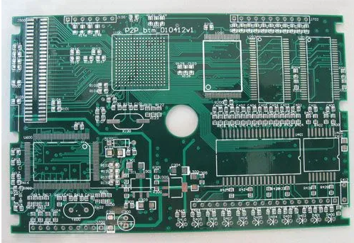
EAGLE is a comprehensive software package that integrates multiple programs, each serving a specific design function. This discussion will concentrate on the “Schematic Editor” and “Board Editor,” while other modules include the Autorouter, Component Editor, CAM processing software (CAM Processor, used for generating machining files), and an interface for programming user-defined language programs (User Language Programs).
We can choose components from the component library, with each component represented by two types of icons, one for the circuit schematic and the other for the circuit board. Since most components originate from different libraries (packages), EAGLE’s component library enables different packages to link to the same component icon. To streamline the process, we have created an RBBB database containing the components necessary for this design. Once you’re familiar with the design process, the SparkFun database will serve as an excellent resource to expand your knowledge.
**EAGLE Workflow**
I. Design and Material Search: Identify parts, review specifications, download necessary files, and create blueprints.
II. Circuit Schematic Design: Connect various components using signal wires.
III. Circuit Rule Check (ErC): Utilize artificial intelligence (AI helper) to identify errors in the circuit.
IV. Circuit Board Design: Position the designed components on the circuit board and create physical connections.
V. Design Rule Check (DrC): Use AI to verify design errors.
VI. Generate Gerber and Drill Files: Use CAM processing software to create machining files.
1. **Getting Started**
First, download the EAGLE Light Edition from the Cadsoftusa.com website and acquire the RBBB component database from moderndevice.com/downloads. Place the package in the lbr database within the EAGLE program.
EAGLE distinguishes layers with different functions in CAD drawings using color. In the “Circuit Schematic Editing” window, the component icon appears in the “Symbols layer,” while its label resides in either the “Names layer” or “Values layer.” The network connections (Net) are found in the “Net layer.” You can show or hide these layers via the View Menu.
**Tip:** Regularly check your toolbar to ensure you are drawing on the correct layer.
1.1 Open the schematic editor and navigate to “File” – “New” – “Schematic.” A warning message will appear stating, “No forward/backward annotation will be performed.” This is because typically, the schematic diagram and board editor are opened simultaneously and synchronized; the message indicates that the PCB file has not yet been opened.
1.2 Select the “Add” tool and position the Frame component from the RBBB component database onto the workspace. While this step is optional, it simplifies the process of drawing the circuit schematic without constant adjustments to the screen size.
2. **Power Circuit**
These five components manage the reception of DC power input and output a noise-free 5V power supply. The central icon represents a voltage regulator. Key specifications for the voltage regulator include output voltage, maximum output current, and dropout voltage (the minimum difference between input and output potential). The L4931 voltage regulator has a minimal dropout voltage of only 0.4V, making it reliable for outputting 5V from a 6V input (such as from four AA batteries). It can supply up to 250mA, which is ample for most microcontroller applications.
**Rules of Thumb**
– A small dot signifies that two intersecting signal lines are connected; no dot indicates they merely overlap.
– Utilize the Grid tool, setting its size to 0.1 inch (100 mil), as a common mistake is assuming two lines intersect when they do not.
– Each line (network connection or signal line) has an independent name. Even if not adjacent, all signal lines sharing the same name will be automatically connected, simplifying complex designs.
– Each component should have a clear name and value. Adjust the labels to ensure clarity and legibility; use the Smash tool to separate labels from components and reposition them as needed.
– Drawing a schematic is akin to communicating with circuit components. Consider whether you’ve provided all the necessary functions.
2.1 Use the “Add” tool to select RBBB – Regulator and place the Regulator component in the upper left quadrant of the screen. Then, use the Add tool to configure two Electrolytic_Caps components, along with GND and +5V signal supply components (RBBB – Supply).
2.2 Connect the output and input of the voltage regulator to the positive terminals of the two capacitors using the “Net” tool. Then, connect the negative terminal of the capacitor to the ground pin of the voltage regulator, linking the ground to the PCB GND component, and connect the output terminal of the voltage regulator to the +5V signal supply component.
2.3 Set both capacitors to 47μF using the Value tool.
2.4 Add the RBBB-Power_Jack and position it next to the input terminal of the voltage regulator. This is a standard center-positive power socket (except for musical equipment). Connect its center pin to the input of the voltage regulator and the sleeve to ground. If prompted by the “Connect Net Segments?” dialog, select “Yes.”
2.5 Introduce a new diode, which will appear horizontally. Use the “Rotate” tool to position the negative side upwards, and use the “Network Connection” tool to connect it between the input of the voltage regulator and ground.
2.6 Lastly, add a 1*2 header (RBBB-1x2_Pinhead) for optional power input, rotate it, and place it accordingly, connecting one pin to the power supply and the other to ground.
—
This version maintains your original intent while enhancing clarity and coherence.

