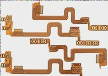
If the frequency of the digital logic PCB board reaches or exceeds 45MHZ~50MHZ, and the circuit working above this frequency has accounted for a certain amount of the entire electronic system (for example, 1/3), it is usually referred to as a high-frequency circuit. Designing high-frequency circuits is a complex process, and routing plays a critical role in the overall design.
Multilayer board wiring
High-frequency circuits often require high integration and high wiring density. The use of multilayer boards is essential not only for wiring but also as an effective means to reduce interference. During the PCB layout stage, choosing a suitable size for the printed board with a certain number of layers allows for optimal use of the middle layers to create shields, achieve the closest grounding, and reduce parasitic inductance while shortening the signal transmission length. These practices can significantly decrease signal cross-interference and enhance the reliability of high-frequency circuits. Research indicates that the noise levels of a four-layer board are 20dB lower than those of a double-sided board when using the same materials. However, increasing the number of layers in the PCB can complicate the manufacturing process and raise the unit cost. Therefore, it is crucial to carefully select the number of layers during PCB layout, plan the component layout effectively, and adhere to proper routing guidelines to successfully complete the design.

2. The fewer lead bends between the pins of high-speed electronic devices, the better. The leads of the high-frequency circuit wiring are all straight lines and need to be minimized. They can be turned with 45-degree broken lines or arcs. This requirement is used to improve the fixing strength of the copper foil in the low-frequency circuit. However, in the high-frequency circuit, meeting this requirement can reduce external emission and mutual coupling of high-frequency signals.
3. The shorter the lead between the pins of the high-frequency circuit device, the better. The radiation intensity of the signal is proportional to the trace length of the signal line. The longer the high-frequency signal lead, the easier it is to couple to components close by. Therefore, for signals like clocks, crystal oscillators, DDR data, high-frequency signal lines like LVDS lines, USB lines, and HDMI lines, it is crucial to keep them as short as possible.
4. The fewer alternations between the lead layers between the pins of the high-frequency circuit device, the better. “The less interlayer alternation of the leads, the better” refers to minimizing the number of vias used in the component connection process. Each via can introduce around 0.5pF of distributed capacitance, reducing vias can significantly improve speed and reduce the likelihood of data errors.
5. Pay attention to the “crosstalk” caused by close parallel traces of signal lines. In high-frequency circuit wiring, be mindful of the “crosstalk” resulting from parallel wiring of signal lines in close proximity. Crosstalk is the coupling phenomenon between indirectly connected signal lines. To reduce crosstalk of high-frequency signals, consider the following when wiring: Insert a ground wire or ground plane between lines with severe crosstalk if space permits. Grounding can isolate and reduce crosstalk. Additionally, increase spacing between adjacent signal lines, minimize parallel length, and ensure clock lines are perpendicular to key signal lines to reduce crosstalk.
6. Add high-frequency decoupling capacitors to the power pins of integrated circuit blocks. Installing high-frequency decoupling capacitors on power pins can effectively suppress interference caused by high-frequency harmonics.
7. Isolate the ground wire of high-frequency digital signals from analog signals. When connecting analog and digital ground wires to a common ground, use high-frequency choke magnetic beads for connection or isolate and interconnect at a suitable point. Ground potential differences between high-frequency digital signal ground wire and analog signal ground wire can introduce voltage differences, potentially causing interference through ground wire coupling. Isolating the ground wire of high-frequency digital signals from analog signals can help prevent this interference.
8. Avoid loops formed by traces. High-frequency signal traces should avoid forming loops as much as possible. If unavoidable, minimize the loop area.
9. Ensure good signal impedance matching. Maintaining impedance matching in signal transmission is essential to avoid reflection and signal instability. Impedance of the transmission line should match the load impedance as closely as possible to minimize reflections. When wiring high-speed PCB boards, follow specific rules for USB, HDMI, LVDS, and DDR routing to ensure impedance matching.
10. Maintain signal integrity. Prevent the “ground bounce phenomenon” caused by ground wire splitting on the PCB board to maintain signal integrity during transmission.
Multilayer board wiring
High-frequency circuits often require high integration and high wiring density. The use of multilayer boards is essential not only for wiring but also as an effective means to reduce interference. During the PCB layout stage, choosing a suitable size for the printed board with a certain number of layers allows for optimal use of the middle layers to create shields, achieve the closest grounding, and reduce parasitic inductance while shortening the signal transmission length. These practices can significantly decrease signal cross-interference and enhance the reliability of high-frequency circuits. Research indicates that the noise levels of a four-layer board are 20dB lower than those of a double-sided board when using the same materials. However, increasing the number of layers in the PCB can complicate the manufacturing process and raise the unit cost. Therefore, it is crucial to carefully select the number of layers during PCB layout, plan the component layout effectively, and adhere to proper routing guidelines to successfully complete the design.

2. The fewer lead bends between the pins of high-speed electronic devices, the better. The leads of the high-frequency circuit wiring are all straight lines and need to be minimized. They can be turned with 45-degree broken lines or arcs. This requirement is used to improve the fixing strength of the copper foil in the low-frequency circuit. However, in the high-frequency circuit, meeting this requirement can reduce external emission and mutual coupling of high-frequency signals.
3. The shorter the lead between the pins of the high-frequency circuit device, the better. The radiation intensity of the signal is proportional to the trace length of the signal line. The longer the high-frequency signal lead, the easier it is to couple to components close by. Therefore, for signals like clocks, crystal oscillators, DDR data, high-frequency signal lines like LVDS lines, USB lines, and HDMI lines, it is crucial to keep them as short as possible.
4. The fewer alternations between the lead layers between the pins of the high-frequency circuit device, the better. “The less interlayer alternation of the leads, the better” refers to minimizing the number of vias used in the component connection process. Each via can introduce around 0.5pF of distributed capacitance, reducing vias can significantly improve speed and reduce the likelihood of data errors.
5. Pay attention to the “crosstalk” caused by close parallel traces of signal lines. In high-frequency circuit wiring, be mindful of the “crosstalk” resulting from parallel wiring of signal lines in close proximity. Crosstalk is the coupling phenomenon between indirectly connected signal lines. To reduce crosstalk of high-frequency signals, consider the following when wiring: Insert a ground wire or ground plane between lines with severe crosstalk if space permits. Grounding can isolate and reduce crosstalk. Additionally, increase spacing between adjacent signal lines, minimize parallel length, and ensure clock lines are perpendicular to key signal lines to reduce crosstalk.
6. Add high-frequency decoupling capacitors to the power pins of integrated circuit blocks. Installing high-frequency decoupling capacitors on power pins can effectively suppress interference caused by high-frequency harmonics.
7. Isolate the ground wire of high-frequency digital signals from analog signals. When connecting analog and digital ground wires to a common ground, use high-frequency choke magnetic beads for connection or isolate and interconnect at a suitable point. Ground potential differences between high-frequency digital signal ground wire and analog signal ground wire can introduce voltage differences, potentially causing interference through ground wire coupling. Isolating the ground wire of high-frequency digital signals from analog signals can help prevent this interference.
8. Avoid loops formed by traces. High-frequency signal traces should avoid forming loops as much as possible. If unavoidable, minimize the loop area.
9. Ensure good signal impedance matching. Maintaining impedance matching in signal transmission is essential to avoid reflection and signal instability. Impedance of the transmission line should match the load impedance as closely as possible to minimize reflections. When wiring high-speed PCB boards, follow specific rules for USB, HDMI, LVDS, and DDR routing to ensure impedance matching.
10. Maintain signal integrity. Prevent the “ground bounce phenomenon” caused by ground wire splitting on the PCB board to maintain signal integrity during transmission.


