PCB Design Best Practices for Switching Power Supply
When designing a switching power supply, the PCB board’s physical design plays a critical role in ensuring stable operation and minimizing electromagnetic interference. Here are some key considerations to keep in mind:
- Design Process: From schematic diagram to PCB board, ensure to establish component parameters, input schematic netlist, set design parameters, layout components, route traces, verify design, review, and output CAM file.
- Parameter Setting: Maintain proper spacing between traces for electrical safety, use wider spacing for ease of production, ensure sufficient trace spacing, and design pads with a distance greater than 1mm from the edge to prevent defects.
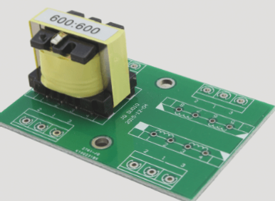
Component layout is crucial for the reliability of electronic equipment. Improper PCB design can lead to performance degradation, such as signal waveform delay and reflection noise. Each switching power supply comprises four current loops:
- AC circuit of the power switch
- Output rectifier AC circuit
- Input signal source current loop
- Output load current loop
The layout of these current loops is essential to minimize electromagnetic interference. Proper placement of components like filter capacitors, power switches, and inductors is crucial for efficient operation. Follow these principles when laying out components:
- Consider PCB board size to prevent long printed lines
- Avoid overly dense device placement
- Design around functional circuit elements
- Arrange components based on circuit flow
- Ensure efficient routing and minimize loop areas
By adhering to these best practices, you can optimize the PCB design for your switching power supply, ensuring reliable and stable operation.
Optimizing PCB Layout for Switching Power Supplies
When designing a switching power supply, it’s important to consider the impact of high-frequency signals on printed wires. Any wire can act as an antenna, with its length and width affecting impedance and inductance, thus influencing frequency response.
To minimize interference, AC-carrying traces should be short and wide, and components should be placed close together. Grounding plays a vital role as a common reference point for controlling interference. Proper single-point grounding and thickening of ground wires are crucial for stability and anti-noise performance.
For local switching power supplies, it’s essential to interconnect input and output grounds to ensure a common reference ground. After designing the wiring layout, thorough checks must be conducted to ensure compliance with designer rules and production requirements.
When generating output files, attention to detail is key. This involves layer outputs, silk screen layers, solder mask layers, drilling layers, and the creation of drill files (NC Drill). Careful selection of settings and layers is necessary to accurately output the required files.