The STM8S001J3 Microcontroller and Programmable Police LED Flasher
The STM8S001J3 is an 8-bit microcontroller with 8 Kbytes of Flash memory and an integrated data EEPROM. This device is ideal for creating a programmable Police LED Flasher for vehicles, motorcycles, and bicycles.
Circuit Analysis
Figure 1 displays the schematic diagram of the device, highlighting the STM8S001 microcontroller as the central component.
We start the analysis with the power supply unit. Capacitors C2 and C3 reduce input voltage noise, regulated by the 78M09 to stabilize the voltage at 9V. Further noise reduction is achieved through capacitors C4, C6, and a first-order RC filter (R28 and C5).
The MCU (IC1) is powered by REG2, stepping down the voltage to 5V. Programming is done via a Single-Wire Interface Module (SWIM), connecting the MCU to the programmer/debugger.
Logic N-Channel SMD MOSFETs (IC2 and IC3) control the LEDs, with push-button switch SW1 toggling between flasher programs. Proper current-limiting resistors (R1 to R26) ensure safe LED operation.
For series-connected LEDs, selecting the right resistor value is crucial. Starting with a 100-ohm resistor and monitoring the current can help determine the optimal value.
PCB Layout
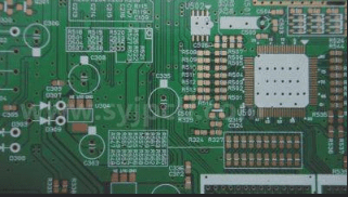
Figure 3 showcases the PCB layout of the Police LED Flasher, a single-layer design with surface-mount components. Libraries from SamacSys were utilized for placing components, saving time and ensuring adherence to IPC footprint standards.
Utilizing the Altium Designer plugin with SamacSys libraries simplified component placement, reducing errors that could impact prototypes. The final PCB layout is shown in Figure 4.
Figures 5 and 6 provide 3D views of the completed PCB revision, offering a comprehensive look at the design.
PCB Prototype Development Updates
Figure 6: 3D view of the PCB (bottom side, final revision)
Figure 7: First Prototype of the Flasher Board
In the latest revision of the PCB prototype, modifications were made to component footprints and the placement of supply wires. The 12V supply wires are now directly soldered onto the bottom side of the PCB for improved efficiency.
Software Development for STM8 Microcontrollers
The STM8 microcontrollers are known for their reliability, but users currently face challenges with software support. While STM8CubeMX does not fully support STM8s, developers can utilize ST Visual Develop (STVP) as an IDE along with pre-written libraries (STSW) for programming. Installing the COSMIC STM8 compiler for STVP is also necessary.
Figure 8 illustrates the STVP IDE used for programming STM8 microcontrollers.
Creating Flashing Programs
GPIO and external interrupt libraries were employed to develop three distinct flashing programs for the PCB prototype. The software is open-source, allowing users to customize and expand the codebase. For a detailed guide, refer to the linked YouTube video.
Assembly and Testing Guidelines
Figure 9: Bill of Materials
During assembly, attention must be paid to connecting LEDs correctly by observing polarities. Consistent illumination can be achieved by using LEDs from the same manufacturer. Properly connect jumpers on the board using zero-ohm resistors. Programming the chip involves uploading the program via an STM programmer with SWIM support and cycling through different flashing programs with a push button.
Additional Resources
- [1]: L78M Datasheet
- [2]: LM1117 Datasheet
- [3]: STM8S001J3 Datasheet
- [4]: SIHFL110 Datasheet
- [5]: Component Search Engine: Part 1049204
- [6]: Component Search Engine: Part 4735
- [7]: Component Search Engine: Part 4735
- [8]: Component Search Engine: Part 179508
- [9]: Component Search Engine: Part 235673
- [10]: Altium Designer Library Instructions
Contact info@wellcircuits.com for PCB and PCBA inquiries.


