Measuring AC Load Parameters with an Energy Meter Circuit
Working with 110V/220V AC mains voltage and measuring the AC load parameters can be challenging for electronic designers. Inductive loads, causing phase shifts and signal distortion, add complexity to the task. In this project, a circuit using an STM32 Microcontroller accurately measures AC RMS voltage, RMS current, power factor, and energy consumption.
The schematic and PCB design were created using Altium Designer 23, with collaboration facilitated through Altium 365. Octopart was used for component sourcing, and Wellcircuits for PCB production. Calibration was done with a Siglent SDM3045X multimeter for precision.
This device offers a 0.5% or better measurement accuracy and features a 1.3-inch OLED display for clear readouts. Download the Gerber files for DIY PCB assembly or order fully assembled PCBs for convenience.
Enhance Your Electronics Projects Today!
Circuit Analysis
Figure 1 displays the schematic diagram of the circuit’s AC mains input and shunt resistor, essential for load monitoring and protection.
Key Components:
- F1: 500mA fuse
- R1: 7D471 varistor
- T1: 10mH common-mode choke
- C1: 100nF-X2 capacitor
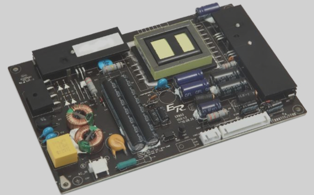
For the power supply section (Figure 2), a mix of isolated and non-isolated outputs is utilized for safe and efficient operation.
Notable Elements:
- C2: 470nF-630V capacitor
- D1, D3: 1N4007 diodes
- U1: HLK-PM01 AC-to-DC module
Figure 3 showcases the measurement segment with the HLW8032 chip and PC817 optocoupler, crucial for accurate data collection.
Measurement Section of the Circuit
C8 and C9 act as decoupling capacitors to minimize noise in the IC1 power supply. R10 controls the current flowing through the optocoupler diode, while R11 serves as a pull-up resistor for the transistor’s collector. Additionally, resistors R13 to R17 lower the input voltage to IC1, and C12 filters out high-frequency noise.
Microcontroller Section of the Circuit
Within this section, Figure 4 illustrates the microcontroller setup, predominantly featuring the STM32G030F6 microcontroller [11]. R18 to R21 function as pull-up resistors, and C13 to C16 serve as debouncing capacitors for switches SW1 to SW4. The OCS denotes the 16MHz oscillator XO [12], which supplies the MCU with its clock signal. T2, T3 [13], along with R22 and R23, facilitate level conversion between the MCU and the OLED display module.
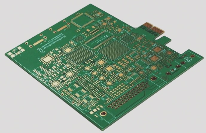
PCB Layout
Figure 5 displays the PCB layout of the design, showcasing a two-layer PCB with a combination of SMD and through-hole components. For further insight, Figure 6 presents the wiring diagram of the board, while Figure 7 exhibits the fully assembled PCB. If you are new to PCB assembly or pressed for time, you have the option to order the fully assembled board.