FPC: Flexible Printed Circuit Boards
FPC, short for Flexible Printed Circuit, is also known as a soft board. It is created by forming conductive circuit patterns on a flexible substrate through light imaging pattern transfer and etching processes. The circuit pattern’s surface is safeguarded and insulated by a layer of polyimide (PI) and adhesive.
- Single-sided boards
- Hollow boards
- Double-sided boards
- Multi-layer boards
- Rigid-flex boards
Advantages of Flexible Circuit Boards
Flexible printed circuit boards (FPCs) offer numerous benefits:
- Flexibility for bending, winding, and folding
- Reduction in size and weight of electronic products
- Excellent heat dissipation and solderability
- Easy assembly and lower overall costs
Main Raw Materials of FPC
The primary raw materials include:
- Base material
- Cover film
- Reinforcement
- Other auxiliary materials
Substrate
Substrates for FPCs can be adhesive or non-adhesive:
- Adhesive Substrate: Consists of copper foil, adhesive, and polyimide (PI).
- Non-Adhesive Substrate: Comprising only copper foil and PI, offering better dimensional stability and other advantages.
Copper Foil
Commonly used copper foil thicknesses include 1OZ, 1/2OZ, and 1/3OZ, with a new thinner option at 1/4OZ being introduced. This material enables the production of ultra-fine circuits.
Cover Film
The cover film consists of release paper, adhesive, and PI. It protects the adhesive during production.
Reinforcement
Reinforcement materials, such as FR4, steel sheet, and PI, are used to enhance support strength in FPCs.
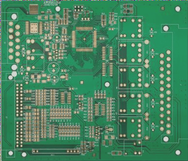
PCB: Printed Circuit Boards
PCB, or Printed Circuit Board, is commonly referred to as a hard board.
If you need more information, feel free to reach out!

Other Auxiliary Materials
- Pure Adhesive: This heat-curing acrylic adhesive film includes protective paper/release film and a layer of glue. It is commonly used for layered boards and flexible/rigid boards to ensure effective bonding.
- Electromagnetic Shielding Film: This film is applied to the board surface to provide protection.
- Pure Copper Foil: Made entirely of copper foil, this material is primarily utilized in hollow board production.
Types of Flexible Printed Circuits (FPC)
- Single Panel: These FPCs have wiring on only one side.
- Double Panel: FPCs with wiring on both sides.
- Hollow Board: Also known as a window board, featuring openings on the surface.
- Layered Board: FPCs with a two-sided circuit that is separate.
- Multilayer Boards: FPCs containing circuits with more than two layers.
- Rigid-Flex Board: A combination of soft and hard boards.
Future Innovations in Flexible Printed Circuits (FPC)
- Thickness: Future FPCs are expected to be more flexible and thinner to meet evolving demands.
- Folding Resistance: Enhanced bending capabilities will be crucial for future FPCs to ensure greater resistance to folding.
- Process Level: FPC processes need to be upgraded to accommodate smaller apertures and adhere to stricter standards for line width and spacing to meet diverse requirements.


