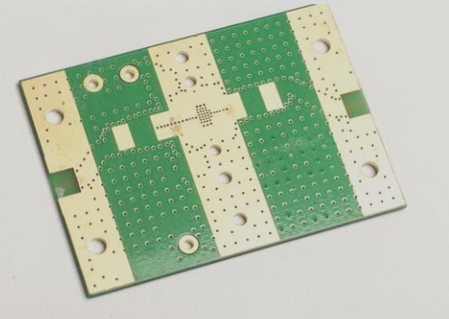
1. Generally speaking, in addition to the normal assembly and testing processes, electronic finished PCB product assembly plants will establish several control checkpoints for testing and inspection to ensure the quality of their production line products.
2. The most commonly seen checkpoints are set at the intermediate stations of product assembly and electrical testing.

Tapping test
The main purpose of tapping is to check for any faulty assembly in the finished product. This includes removing empty or false solder, solder balls, solder beads on electronic parts, and checking if the mechanism and screws are assembled properly. The tapping test rod is usually made by attaching an elastic ball to a wooden rod. When tapping, hold one end of the wooden rod and use the elastic ball to tap the finished product. It is recommended to have the power turned on when tapping. For products with images, pay attention to any abnormalities in the images, as some electronic parts with poor soldering may only have open or short circuit problems when tapped. Usually, the tapping test is conducted before the electrical test, as the product’s issues may not be revealed until after tapping. If there is no electrical test after tapping, defective products may end up being sent to the customers. The location of tapping is crucial, as different positions will have different effects. Tap where resonance can occur in the product’s solid, and generally tap three times in succession. It is best to tap on the most vulnerable part of the product design. Only tapping in hollow places will not be effective. Additionally, the size and weight of the elastic ball will affect the tapping effect, so it’s important to pay attention to these factors.
Drop test
The drop test refers to the quality verification of products before shipment and not the DQ (Design Quality) drop test. It is focused on checking for any damage to the product itself. The goal is similar to the tapping test, and both tests complement each other in checking for faulty assembly in the finished product. The tapping test focuses on resonance and involves tapping three times in succession, while the drop test only involves one drop. The surface for the drop test is made of solid wood with a layer of 3~5mm electrostatic table mat. During the drop test, the product is allowed to fall freely without power supply or being powered on. As with the tapping test, an electrical test must be conducted after the drop test to ensure that the product functions properly and has no visible damage. The drop height usually ranges from 76.2 mm (3 inches) to 300 mm, depending on the weight of the product. The heavier the weight, the lower the drop height. Personal experience has shown that production line operators may not be afraid to drop products, resulting in the drop test being conducted at lower heights. Operators should understand that the purpose of the drop test is to identify defective products before they reach the customers, rather than risking damage to the product during its use by a customer.
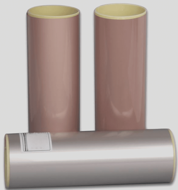
Furthermore, it has been noted that some flexible circuit boards (FPCs) have had issues with line breaks. In order to make the FPCs lighter and thinner, a switch was made from 1/2 ounce to 1/3 ounce copper foil a few years ago. However, the thinner copper foil has reduced ability to withstand bending, known as rolled copper. Defective products were initially returned with open circuit issues, but the break in the copper foil line was not initially visible. Upon further investigation and bending of the FPC, it was discovered that the copper foil line had broken due to lack of support from the PI layer, leading to the fracture after enduring stress. This explanation seems plausible, however, the intermittent nature of the issue suggests that there may be another reason for the FPC line to break. It is important to note that the gap between the copper foil line and the PI layer should be difficult to avoid, and the rolled copper should have enough ductility to withstand such a gap. While this conclusion is accepted, there is still some doubt. If the wrong copper plating was used, it would affect batch production rather than resulting in sporadic cases, indicating that there may be a separate reason for the FPC line to break.
2. The most commonly seen checkpoints are set at the intermediate stations of product assembly and electrical testing.

Tapping test
The main purpose of tapping is to check for any faulty assembly in the finished product. This includes removing empty or false solder, solder balls, solder beads on electronic parts, and checking if the mechanism and screws are assembled properly. The tapping test rod is usually made by attaching an elastic ball to a wooden rod. When tapping, hold one end of the wooden rod and use the elastic ball to tap the finished product. It is recommended to have the power turned on when tapping. For products with images, pay attention to any abnormalities in the images, as some electronic parts with poor soldering may only have open or short circuit problems when tapped. Usually, the tapping test is conducted before the electrical test, as the product’s issues may not be revealed until after tapping. If there is no electrical test after tapping, defective products may end up being sent to the customers. The location of tapping is crucial, as different positions will have different effects. Tap where resonance can occur in the product’s solid, and generally tap three times in succession. It is best to tap on the most vulnerable part of the product design. Only tapping in hollow places will not be effective. Additionally, the size and weight of the elastic ball will affect the tapping effect, so it’s important to pay attention to these factors.
Drop test
The drop test refers to the quality verification of products before shipment and not the DQ (Design Quality) drop test. It is focused on checking for any damage to the product itself. The goal is similar to the tapping test, and both tests complement each other in checking for faulty assembly in the finished product. The tapping test focuses on resonance and involves tapping three times in succession, while the drop test only involves one drop. The surface for the drop test is made of solid wood with a layer of 3~5mm electrostatic table mat. During the drop test, the product is allowed to fall freely without power supply or being powered on. As with the tapping test, an electrical test must be conducted after the drop test to ensure that the product functions properly and has no visible damage. The drop height usually ranges from 76.2 mm (3 inches) to 300 mm, depending on the weight of the product. The heavier the weight, the lower the drop height. Personal experience has shown that production line operators may not be afraid to drop products, resulting in the drop test being conducted at lower heights. Operators should understand that the purpose of the drop test is to identify defective products before they reach the customers, rather than risking damage to the product during its use by a customer.
Furthermore, it has been noted that some flexible circuit boards (FPCs) have had issues with line breaks. In order to make the FPCs lighter and thinner, a switch was made from 1/2 ounce to 1/3 ounce copper foil a few years ago. However, the thinner copper foil has reduced ability to withstand bending, known as rolled copper. Defective products were initially returned with open circuit issues, but the break in the copper foil line was not initially visible. Upon further investigation and bending of the FPC, it was discovered that the copper foil line had broken due to lack of support from the PI layer, leading to the fracture after enduring stress. This explanation seems plausible, however, the intermittent nature of the issue suggests that there may be another reason for the FPC line to break. It is important to note that the gap between the copper foil line and the PI layer should be difficult to avoid, and the rolled copper should have enough ductility to withstand such a gap. While this conclusion is accepted, there is still some doubt. If the wrong copper plating was used, it would affect batch production rather than resulting in sporadic cases, indicating that there may be a separate reason for the FPC line to break.


