**Talking about the V-Cutting Skills of Circuit Boards**
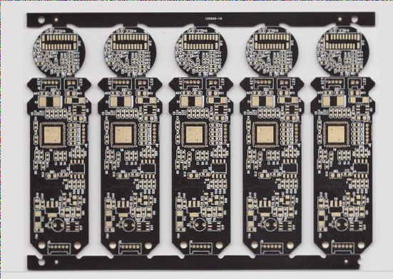
I have covered quite a bit of knowledge related to circuit boards, but I’m not sure how much of it you are familiar with or have absorbed. The term “V-cut” refers to a process where the printed circuit board (PCB) manufacturer cuts dividing lines at specific locations on the PCB according to the customer’s design specifications. These cuts are made using a turntable cutter and are intended to facilitate the “de-paneling” process after the subsequent SMT (Surface Mount Technology) assembly is completed. The appearance of the cut, resembling the letter “V” in English, is why it is called a V-cut.
The V-cutting process on a circuit board is a method used to separate the semi-finished product into smaller units, making it easier for further processing. This technique is similar to perforating a sheet of stamps to allow easy separation. While circuit boards also use perforated holes for this purpose, the primary method is V-cutting, where a V-shaped groove is ground into the PCB using a V-cutting machine. Before initiating the V-cut, it is essential to carefully check the slotting distance. Any significant errors in this distance can result in a single unit being too large or too small. Typically, the V-groove along the edge of the positioning plate is deeper than the grooves between individual units. This ensures that components do not break during soldering but can still be separated easily. If the groove is too deep, however, the board may become too fragile. Therefore, controlling the depth of the V-cut is a critical challenge. The required V-cut depth can vary depending on the material and thickness of the board.

1. Generally, the production of bare circuit boards begins with panelization and break-away operations. Once the circuit board is printed (or pasted) and the parts are assembled, it is then necessary to perform the “dividing” process. The board can only be installed into the machine after this, as typically, no more than two identical assembly boards (PCBA) are installed in the machine at the same time.
2. If the circuit board’s V-cut is too deep and cannot be corrected through rework or repair, it can still be salvaged starting from the SMT (Surface Mount Technology) process, in order to make the PCB as usable as possible. The deep V-cut reduces the number of connected materials and makes the PCB more prone to deformation or even breakage under high temperatures. To prevent this, a mold can be created to support the PCB. For example, placing the PCB in a wire mesh during reflow soldering can help keep it in place, preventing breakage. This allows the PCB to be mounted normally, thus avoiding loss.
3. WellCircuits is a high-tech manufacturing company specializing in the development and production of high-precision PCBs. We are eager to become your trusted business partner. Our mission is to become the world’s most professional PCB prototyping manufacturer. Our main focus includes microwave high-frequency PCBs, high-frequency mixed pressure, ultra-high multi-layer IC testing, ranging from 1+ to 6+ HDI, Anylayer HDI, IC substrates, IC test boards, rigid-flex PCBs, and standard multi-layer FR4 PCBs. Our products are widely used across various industries such as Industry 4.0, communications, industrial control, digital technology, power systems, computing, automotive, medical, aerospace, instrumentation, IoT, and more.
I have covered quite a bit of knowledge related to circuit boards, but I’m not sure how much of it you are familiar with or have absorbed. The term “V-cut” refers to a process where the printed circuit board (PCB) manufacturer cuts dividing lines at specific locations on the PCB according to the customer’s design specifications. These cuts are made using a turntable cutter and are intended to facilitate the “de-paneling” process after the subsequent SMT (Surface Mount Technology) assembly is completed. The appearance of the cut, resembling the letter “V” in English, is why it is called a V-cut.
The V-cutting process on a circuit board is a method used to separate the semi-finished product into smaller units, making it easier for further processing. This technique is similar to perforating a sheet of stamps to allow easy separation. While circuit boards also use perforated holes for this purpose, the primary method is V-cutting, where a V-shaped groove is ground into the PCB using a V-cutting machine. Before initiating the V-cut, it is essential to carefully check the slotting distance. Any significant errors in this distance can result in a single unit being too large or too small. Typically, the V-groove along the edge of the positioning plate is deeper than the grooves between individual units. This ensures that components do not break during soldering but can still be separated easily. If the groove is too deep, however, the board may become too fragile. Therefore, controlling the depth of the V-cut is a critical challenge. The required V-cut depth can vary depending on the material and thickness of the board.

1. Generally, the production of bare circuit boards begins with panelization and break-away operations. Once the circuit board is printed (or pasted) and the parts are assembled, it is then necessary to perform the “dividing” process. The board can only be installed into the machine after this, as typically, no more than two identical assembly boards (PCBA) are installed in the machine at the same time.
2. If the circuit board’s V-cut is too deep and cannot be corrected through rework or repair, it can still be salvaged starting from the SMT (Surface Mount Technology) process, in order to make the PCB as usable as possible. The deep V-cut reduces the number of connected materials and makes the PCB more prone to deformation or even breakage under high temperatures. To prevent this, a mold can be created to support the PCB. For example, placing the PCB in a wire mesh during reflow soldering can help keep it in place, preventing breakage. This allows the PCB to be mounted normally, thus avoiding loss.
3. WellCircuits is a high-tech manufacturing company specializing in the development and production of high-precision PCBs. We are eager to become your trusted business partner. Our mission is to become the world’s most professional PCB prototyping manufacturer. Our main focus includes microwave high-frequency PCBs, high-frequency mixed pressure, ultra-high multi-layer IC testing, ranging from 1+ to 6+ HDI, Anylayer HDI, IC substrates, IC test boards, rigid-flex PCBs, and standard multi-layer FR4 PCBs. Our products are widely used across various industries such as Industry 4.0, communications, industrial control, digital technology, power systems, computing, automotive, medical, aerospace, instrumentation, IoT, and more.


