Combatting COVID-19 with Innovative Electronics Solutions
By Hesam Moshiri, Anson Bao
The ongoing impact of the COVID-19 pandemic has highlighted the importance of proper hand hygiene. To address this, we introduce an automatic hand sanitizer dispenser that utilizes IR sensors to detect hand presence and dispense sanitizer without direct contact. This solution aims to be cost-effective and straightforward, eliminating the need for complex microcontrollers or Arduinos. Two design options are presented, offering flexibility to suit different preferences. The first design incorporates SMD components, while the second design simplifies further by using DIP components on a single-layer PCB.
I. First Design:
[A] Circuit Analysis
The circuit operates by supplying 6V to 12V via the P1 connector. Components like the C6 capacitor reduce supply noise, and the REG-1 AMS1117 LDO regulator stabilizes the voltage at 5V.
Schematic Diagram:

Figure 1: Schematic diagram of the automatic hand sanitizer dispenser (First Design)
The circuit includes components like IR transmitter diode D1, 555 timer IC U1, and IR receiver TSOP1738 U2, which detects 38kHz IR light. A MOSFET drives the DC motor (liquid pump) upon IR reception, with LED indicators for status feedback.
[B] PCB Layout
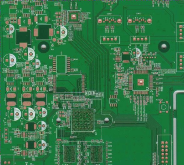
The PCB layout, shown in Figure 2, features mostly SMD components, enhancing compactness and efficiency.

Figure 2: PCB layout of the automatic hand sanitizer dispenser (First Design)
Utilizing SamacSys component libraries for key components streamlines the design process, ensuring adherence to IPC footprint standards and minimizing errors.
Additional Resources:
For a comprehensive guide on designing PCBs for electronic projects, including tips on component selection and layout optimization, refer to our detailed resources.
- PCB Design Best Practices
- Optimizing Component Placement for Efficiency
- Troubleshooting Common PCB Design Issues
Bottom 3D View of the PCB Board
Exploring the underside of a PCB board can reveal crucial insights into its design and functionality. In Figure 5, we witness the intricate details of the bottom 3D view of the PCB board.
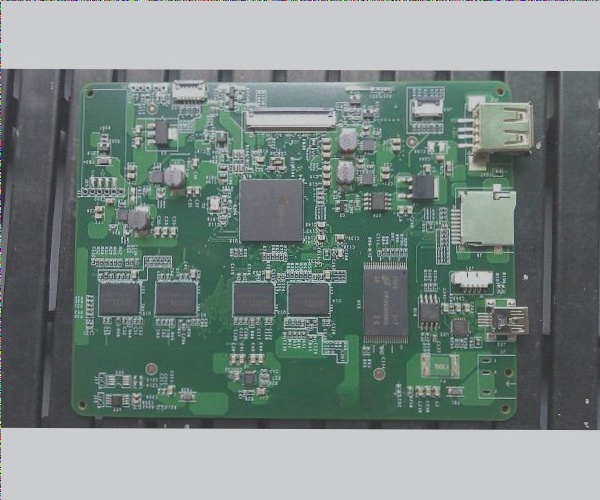
Assembly and Testing
The assembly process for PCB boards has evolved to be more efficient over time. While the components are predominantly SMD, innovations like using professionally fabricated PCB boards can streamline the process further. Figure 6 showcases the prototype of a hand sanitizer dispenser, illustrating the possibilities.
Recent developments in PCB assembly techniques have emphasized the importance of optimizing detection ranges by adjusting specific components like R1 and R4.
Bill of Materials
Understanding the components required for a project is fundamental. The Bill of Materials provides a comprehensive list, ensuring all necessary parts are accounted for in the design process.
Second Design
Circuit Analysis
Delving into the schematic diagram of a device offers a glimpse into its inner workings. Figure 7 presents the schematic diagram of an automatic hand sanitizer dispenser, highlighting key components like the LM393 comparator and its functionalities.
The LM393 series offers precision voltage comparison capabilities, making it a versatile choice for various electronic applications. Utilizing dedicated comparator chips can enhance performance, as demonstrated in this design.
Each component in the circuit serves a specific purpose, from the IR transmitter to the LED indicators, showcasing a meticulous approach to functionality and efficiency.
PCB Layout
The layout of a PCB design plays a crucial role in ensuring seamless integration of components. Figure 8 displays the single-layer PCB layout for the automatic hand sanitizer dispenser, designed for ease of assembly even for DIY enthusiasts.
Utilizing component libraries like SamacSys can significantly expedite the design process and reduce errors, enhancing overall efficiency. Integration with CAD software further streamlines the design workflow, as depicted in Figure 9.
3D View of PCB Assembly
Visualizing the assembled PCB board in a 3D format provides a holistic perspective on the design. In Figure 10, we observe a detailed 3D view of the assembled PCB board, showcasing the culmination of meticulous design and assembly processes.
PCB Assembly and Testing
As shown in Figure 11, the assembled PCB board is a semi-homemade prototype designed for quick concept testing. This PCB is available for fabrication, featuring components in DIP form for easy soldering. The simplified design of this PCB is not only easier to assemble but also more cost-effective, making it the preferred choice for completing the hand sanitizer dispenser device.
Prototype of the sanitizer dispenser (Second Design) on a semi-homemade PCB board
Selected Liquid Pump
Figure 12 displays the selected liquid pump, chosen for its performance despite being a budget-friendly option.
Selected liquid pump for dispensing hand sanitizer liquid
Complete Hand Sanitizer Dispenser
Figure 13 showcases the fully assembled hand sanitizer dispenser. You have the flexibility to use various glass or plastic containers, such as plastic coffee storage containers or glass sauce containers. Simple copper wire can be utilized to secure the hose in place. Adjust the R3 potentiometer gradually to set your desired detection range, avoiding overly sensitive settings that may lead to unintended pump activation.
Complete DIY hand sanitizer dispenser
Dispenser Illumination
Figure 14 provides a view of the hand sanitizer dispenser in the dark, highlighting the attractive glow emitted by the blue LED (P1) mounted on the container lid.
Hand sanitizer dispenser view in the dark
Bill of Materials
A comprehensive list of materials used in the project can be found in the image below:
Bill of Materials
References
- [1]: AMS1117-5.0 Datasheet: http://www.advanced-monolithic.com/pdf/ds1117.pdf
- [2]: LM555 Datasheet: http://www.ti.com/lit/ds/symlink/lm555.pdf?&ts=1589508422474
- [3]: TSOP1738 Datasheet: https://eu.mouser.com/datasheet/2/427/introductionpartnumbers-1766653.pdf
- [4]: NDS356 Datasheet: https://eu.mouser.com/datasheet/2/308/NDS356AP-D-1813031.pdf
- [5]: AMS1117-5.0 Schematic Symbol and PCB Footprint: https://componentsearchengine.com/part.php?partID=2376678
- [6]: LM555 Schematic Symbol and PCB Footprint: https://componentsearchengine.com/part.php?partID=380204
- [7]: TSOP1738 Schematic Symbol and PCB Footprint: https://componentsearchengine.com/part.php?partID=1116997
- [8]: NDS356 Schematic Symbol and PCB Footprint: https://componentsearchengine.com/part.php?partID=840198
- [9]: CAD Plugins: https://www.samacsys.com/library-loader-help
- [10]: LM393 Datasheet: http://www.ti.com/lit/ds/symlink/lm393-n.pdf?&ts=1589509317025
- [11]: BD140 Datasheet: https://www.mouser.com/datasheet/2/149/BD140-888626.pdf
LM393 and BD140 Schematic Symbols and PCB Footprints
- LM393: Check out the schematic symbol and PCB footprint here.
- BD140: Find the schematic symbol and PCB footprint here.
For any inquiries related to PCB and PCBA, don’t hesitate to reach out to me at info@wellcircuits.com.