The Importance of Proper Lithium Battery Charging for Electronic Devices
In today’s digital age, lithium batteries are the powerhouse behind our portable gadgets, ensuring they stay functional and safe for use. To maintain their longevity and prevent potential risks like overheating or explosions, following industry-standard charging practices is crucial. Typically, lithium-ion or lithium-polymer batteries are charged at rates between 0.5C to 1C, ensuring a balance between efficiency and safety.
Introducing a Dual Lithium Battery Charger with Adjustable Charging Current
Explore a versatile dual lithium battery charger that allows you to easily adjust the charging current by modifying a single resistor. This innovative solution only requires a 5V power source, like a mobile charger, and a USB Type-C cable for operation.
Enhanced Design and PCB Layout
For creating the schematic and PCB layout, cutting-edge tools like Altium Designer 22 and the SamacSys component libraries were utilized. To guarantee top-notch PCB fabrication, Gerber files were sent to Wellcircuits, and authentic components were sourced from Componentsearchengine.com. Precise current and voltage measurements during testing were made possible with the Siglent SDM3045X multimeter.
Key Components and Features
- The MCP73831 ICs from Microchip serve as the heart of the charger design, offering advanced linear charge management capabilities in a compact form factor.
- The MCP73831 series supports constant-current/constant-voltage charging with various voltage regulation options to accommodate different battery types.
- Flexible current ranges from 15mA to 500mA make the MCP73831 suitable for a wide range of applications, with stable charging performance even under challenging conditions.
Download and Order Details
- Download the Gerber files or order 10 high-quality boards for just $5
- For inquiries about fully assembled PCBs with free shipping, reach out to anson@wellcircuits.com
By understanding the circuit analysis and PCB layout of this lithium-ion/lithium-polymer USB Type-C charger, you can delve deeper into the intricacies of efficient and safe battery charging practices for your electronic devices.
Using SamacSys Component Libraries for PCB Design
When designing my PCB, I encountered a lack of component libraries for IC1 and IC2. To address this issue, I turned to the IPC-rated SamacSys component libraries. These libraries can be seamlessly integrated into your design using the free SamacSys tools and services. There are two convenient methods for incorporating these libraries: you can either visit componentsearchengine.com or utilize the SamacSys CAD plugin for direct integration into your design environment.

Supported CAD Software for SamacSys Plugins

Using the SamacSys Altium Plugin for Component Library Import

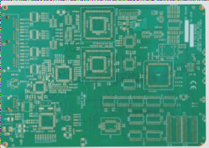
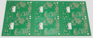
3D View and Assembly Drawings of the PCB
Assembly and Testing of PCB
After importing the necessary component libraries, I proceeded with the assembly of the PCB board. The USB Type-C connector posed a challenge during soldering, requiring specialized equipment such as a hot air station and solder paste. However, soldering the remaining components was relatively straightforward. For those who are new to PCB assembly or prefer pre-assembled boards, fully assembled PCBs are available for purchase.
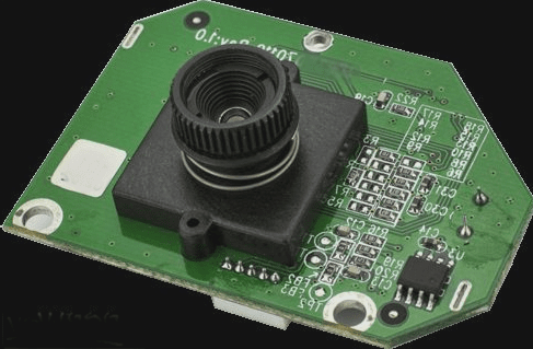
Assembled PCB Board of the Lithium-Ion/Lithium-Polymer USB Type-C Charger
Charging Configuration and Voltage Measurements
I configured the charging current for each channel differently, with one set to 450mA using a 2.2K resistor and the other to 100mA using a 10K resistor. The first channel is dedicated to charging a lithium-ion battery, while the second channel is designed for a small 200mA lithium polymer battery. To monitor the voltage during the charging process, I utilized the Siglent SDM3045X multimeter for accurate measurements.