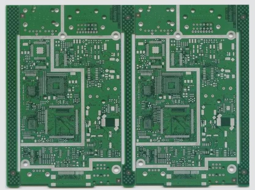
There are multiple steps in the design, processing, and testing of PCB A that require the use of an electric soldering iron for manual welding. The key difference between manual welding with an electric soldering iron and machine welding, such as wave soldering and reflow soldering, is that manual soldering is influenced by various human factors. In contrast, once the process parameters are adjusted for machine welding, production remains stable. Manual welding also presents challenges such as welding temperature and time. In this article, we will discuss the manual lead-free welding process using an electric soldering iron, the welding process window, and the heat transfer principle of the soldering iron to the pad. It is important to grasp the significance of welding temperature and time. Only through theoretical guidance and diligent practice can one become a skilled and qualified worker in this field.

PCB A
Make Preparations Before Welding
1. Before using a new electric soldering iron for the first time, it is important to have a preliminary understanding of its characteristics, such as working voltage, electric power, heat recovery rate, and the size and variety of the soldering iron head.
2. It is crucial to know whether the type of solder is lead-free and the thickness of the melting point tin wire.
3. Understand the type of components, such as plug-in or SMD components and thermal sensitive keys.
4. Have an understanding of the material of the printed board and the plating type of the bonding pad, such as whether it is tin base, gold plating, osp, and their respective parameters. Generally, the temperature of the gold-plated plate should be appropriately higher than that of the tin base plate, and the heat absorption of the multi-layer plate should be greater than that of the double-layer plate and the single-layer plate.
5. Be familiar with the size of the welding spot and the speed of heat dissipation of the welding surface.
6. Consider the anti-static performance of the electric soldering iron and whether the workbench has an anti-static grounding port. Usually, when the electric soldering iron is connected to the power supply, the anti-static channel should also be connected.
In summary, it is very useful to be familiar with the performance of the tool and the basic parameters of the welding object to adjust the temperature and model of the soldering head. Of course, if conditions permit, the welding process parameters can be further confirmed by testing the temperature of the PCBA and PCBA test welding.
Operation Method of Electric Soldering Iron in PCB Processing and Assembly
Operators who use an electric soldering iron for manual welding for the first time should develop good operation habits, achieve a correct welding posture, and master the basic operation steps of welding and the basic essentials of manual welding.
1. Correct Welding Posture
In the manual welding of electronic products, sitting welding is generally adopted. The height of the workbench and seat should be appropriate. The relative position between the operator’s head and the electric soldering iron should be kept at 30~50cm. Hold the soldering iron in one hand and the tin wire in the other hand, and visually weld the points.
2. Method of Holding Electric Soldering Iron by Welding Operator
According to the size of the electric soldering iron, there are three different operation methods: reverse grip method, positive grip method, and pen grip method. The reverse grip method is suitable for the operation of welding large solder joints with high-power electric soldering iron larger than 75 watts. The positive grip method is suitable for the operation of medium-power electric soldering iron and electric soldering iron with elbow. The pen grip method is suitable for the welding of components on printed circuit boards with low-power electric soldering iron, which is mainly used for the manual welding of electronic products.
3. Electric Soldering Iron Contact Solder Joint Direction
When using the pen grip method to weld electronic products, the electric soldering iron should contact the solder joint in a 45-degree direction, which is conducive to operation and observation of the formation of the solder joint.
4. Handling the Tin Wire
There are usually two methods for holding the solder wire, one is suitable for continuous welding, and the other is suitable for intermittent welding. During actual welding operation, wear gloves when holding the solder wire, especially when using lead-containing tin wire, to prevent frequent contact with lead.
5. Basic Operation of Manual Welding
The manual welding operation process can be divided into five steps, which are required to be completed within 3~5 seconds:
5.1. Prepare to approach the soldering head and tin wire to the soldering pad.
5.2. For heating, first place the soldering iron head on the pad, which is the first preheating of the pad.
5.3. Lay the tin wire on the contact part between the soldering iron head and the soldering pad to melt it quickly.
5.4. After the solder joint is formed, remove the tin wire first.
5.5. Remove the electric soldering iron and cool the solder joint into shape.
For small welding spots, the three-step method can also be used to complete the PCBA welding, and steps bc and steps de in the five-step method can be combined into one.


