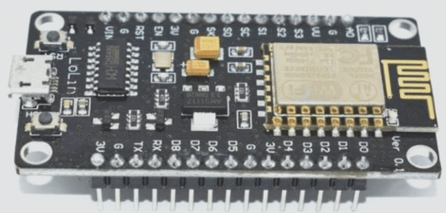
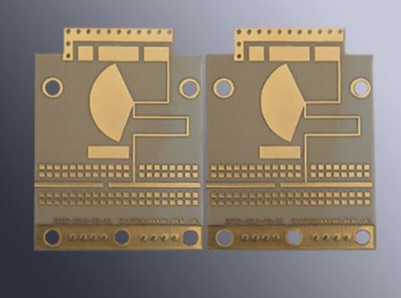
From PCB board design of the single-chip microcomputer to software processing, the focus is on addressing electromagnetic compatibility (EMC).
1. Factors affecting EMC
1.1 Voltage: Higher supply voltage results in greater voltage amplitude and increased emissions, while lower supply voltage affects sensitivity.
1.2 Frequency: Higher frequencies generate more emissions; periodic signals also contribute significantly. In high-frequency microcontroller systems, switching devices cause current spikes. Similarly, in analog systems, changes in load current induce current spikes.
1.3 Grounding: Improper grounding is a primary cause of EMC issues. Three grounding methods exist: single-point, multi-point, and hybrid. Single-point grounding is suitable for frequencies below 1MHz but inadequate for higher frequencies. Multi-point grounding is preferred for high-frequency applications. Hybrid grounding combines single-point for low frequencies and multi-point for high frequencies. Proper layout of ground wires is crucial; high-frequency digital and low-level analog circuits should ideally have separate grounds.
1.4 PCB Board Design: Correct PCB routing is crucial in minimizing EMI.
1.5 Power Supply Decoupling: During device switching, transient currents occur on the power supply line, necessitating attenuation and filtering. High di/dt sources generate transient currents that induce voltage spikes on grounds and traces, and excite components, leading to cable radiation. Changes in current flow and inductance cause voltage drops, which can be mitigated by reducing inductance or modifying current flow over time.
2.1 Electromagnetic Compatibility Design of Printed Circuit Boards (PCB)
The PCB serves as the foundation for circuit components and devices within single-chip microcomputer systems, facilitating electrical connections. As electronic technology advances, PCB density increases, underscoring the critical impact of PCB design quality on electromagnetic compatibility. Poor PCB design, despite correct circuit schematics, can detrimentally affect single-chip microcomputer system reliability. For instance, closely spaced parallel lines on a PCB may cause signal waveform delays and reflection noise. Hence, PCB design should adhere to proper methodologies, general principles, and interference resistance requirements to ensure optimal electronic circuit performance.
2.2 Electromagnetic Compatibility Design of Input/Output
In single-chip microcomputer systems, input/output functions as both a conduit for interference and a receiver of radio frequency interference signals. Effective design measures include: (1) implementing necessary common mode/differential mode suppression circuits, along with filtering and electromagnetic shielding to mitigate interference; (2) utilizing isolation techniques (e.g., optoelectronic or magnetoelectric isolation) to curtail interference propagation.
2.3 Design of MCU Reset Circuit
The watchdog system is pivotal in single-chip microcomputer operation, providing critical error correction defense when CPU interference disrupts program execution. Two commonly employed reset systems are: (1) External reset, utilizing a watchdog circuit either custom-designed or integrated with a dedicated chip. Dedicated chips may lack responsiveness to low-frequency “feed the dog” signals, necessitating band-pass “feed the dog” circuitry for effective monitoring. (2) Increasingly, single-chip microcomputers feature on-chip reset systems, although some models may have limited reset functionalities, impacting reliability under certain conditions.
2.4 Oscillator
Most microcontrollers incorporate an oscillator circuit linked to external crystals or ceramic resonators. PCB layouts should minimize lead lengths for external capacitors, crystals, or ceramic resonators. Crystal or ceramic resonators are preferred over RC oscillators due to their susceptibility to interference signals and potential for generating brief clock cycles. Quartz crystal casings should be grounded to optimize performance.
2.5 Lightning Protection Measures
Outdoor use or external power and signal lines necessitate robust lightning protection. Common devices include gas discharge tubes and TVS (Transient Voltage Suppression) diodes. Gas discharge tubes conduct strong impulse pulses to ground when power supply voltage exceeds a threshold, while TVS diodes, akin to parallel zener diodes, transiently pass high currents to safeguard against voltage spikes.
3. Software Processing Method for Interference Measures
Electromagnetic interference can affect CPU-processed units, particularly in environments with harsh electromagnetic conditions. RAM, susceptible to bistable storage disruption, may flip stored values (e.g., ‘0’ to ‘1’ or vice versa), alter transmission timings, corrupt critical data parameters, and compromise system reliability. Effective software design is crucial for enhancing system anti-interference capabilities.
3.1 Program Behavior under Electromagnetic Interference
Electromagnetic interference can cause program runaway or induce infinite loops and abnormal program behavior, resulting in unpredictable code execution and potential data corruption. Robust reset systems and well-structured software frameworks mitigate such impacts on system stability.
3.2 Storage of Important Parameters
Error detection and correction mechanisms play a vital role in preventing data corruption due to interference. By adding redundancy codes during data writing and employing error detection algorithms during data reading, systems can automatically correct single-bit errors and generate exceptions for two-bit errors, ensuring data integrity and system reliability.
3.3 RAM and FLASH (ROM) Testing
Periodic testing of RAM and FLASH (ROM) during programming detects errors promptly, enabling timely corrections or user notifications. Program redundancy, such as adding NOP instructions, and integrating flags and state detection during program execution, further enhance error detection and correction capabilities on PCB boards.