Rigid-Flex PCBs: Revolutionizing Circuit Board Design
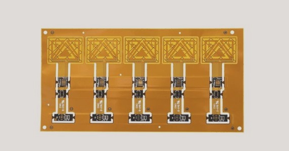
Rigid-flex PCBs are transforming the landscape of circuit board design. By seamlessly integrating thin layers of flexible and rigid substrates into a single component, designers are faced with unique challenges and exciting opportunities.
Advanced Design Capabilities
Designing rigid-flex PCBs goes beyond traditional two-dimensional layouts. It involves creating a three-dimensional internal connection that can be bent and folded, optimizing space and enhancing performance.
Enhanced Performance and Stability
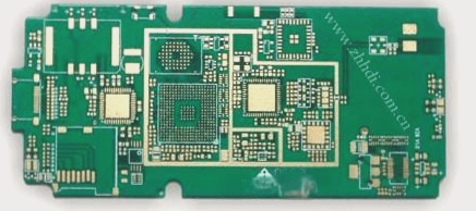
Rigid-flex boards offer a more advanced alternative to composite printed circuit boards. By consolidating multiple connectors, cables, and ribbon cables into a single component, these boards deliver improved performance and stability.
Dynamic Flexibility
Flex circuits, commonly referred to as “dynamic flex,” provide continuous flexibility for high performance and reliability. They are ideal for applications requiring interconnections between subsystems.
Rigidized Flex Circuits
Rigidized flex circuits combine the flexibility of flex circuits with the reinforcement of rigid materials. By strategically positioning rigid materials within the flex circuit, specific areas can be strengthened for single-sided component placement.
Multi-Layer Rigid-Flex PCBs
Rigid-flex boards feature both rigid and flexible layers, making them ideal for applications that demand double-sided module installation or ultra-thin printed circuit boards. These multi-layer boards offer a versatile solution for complex design requirements.
Applications in Consumer Electronics and Aerospace
Rigid-flex boards are widely used in consumer electronics such as digital cameras and MP3 players. They also play a crucial role in high-end aerospace systems, where they reduce weight, increase connection reliability, and optimize space.
Impact in Military and Medical Fields
In military aircraft, rigid-flex panels offer weight reduction and enhanced reliability, contributing to overall system efficiency. In the medical field, implantable devices like pacemakers benefit from the flexibility and reliability of rigid-flex boards.
Future Innovations with Rigid-Flex Boards
Designers are leveraging rigid-flex boards to achieve product goals efficiently. By using rigid designs as prototypes and transitioning to rigid-flex boards for new products, they can meet stringent space and weight requirements without compromising functionality.

Revolutionizing PCB Design with Rigid-Flex Boards
1. The key to success in a recent project was the replacement of a rigid PCB assembly with flexible rigid-flex boards, resulting in a weight reduction from 3 pounds to under 3 ounces.
2. Jeff, a newcomer to rigid-flex boards, demonstrated exceptional skills by collaborating with an experienced designer for the PCB layout.
3. Early engagement with PCB manufacturers and careful evaluation of the increased cost associated with rigid-flex boards played a vital role in achieving the project’s objectives.
4. The flexibility and foldability of rigid-flex boards enable the creation of custom circuits that optimize space utilization indoors, offering significant advantages in unique designs despite higher production expenses.
5. Designing a rigid-flex panel demands a deep understanding of the manufacturing process and material characteristics, as conventional traces from rigid PCBs may not produce the desired outcomes.
6. The steric stability of polyimide is notably lower than that of FR4, leading to material shrinkage post-etching.
7. Manufacturers address this shrinkage by meticulously adhering to dimensional tolerances during the machining phase.
8. Designers need to anticipate potential manufacturing challenges by incorporating teardrops at junctions and maximizing plated via ring sizes on the flex layer to achieve the desired outputs.
9. Connecting rigid and flexible regions requires considerations such as supporting floating rigid areas during manufacturing and avoiding excessive removal of rigid material to prevent board fragility.
10. Die cutting is the preferred method for flex layers due to its compatibility with thin polyimide, and design tools should include no-routing areas to prevent routing components or lines over rigid edges.
11. To reduce conductor stress in flex circuits, route traces perpendicular to bend areas, avoid chamfers and width changes within bend areas, and utilize a grid of copper instead of solid copper.
12. For in-depth insights and design tips, consult the recommended resources on flex circuit design.
13. Some manufacturers recommend transitioning from rigid-flex to rigid boards due to cost considerations, underscoring the importance of early involvement in high-volume production.
14. The primary cost factors for rigid-flex boards include raw materials, board utilization, and yield, with early collaboration aiding in minimizing design flaws and expenses.
15. When selecting a supplier for flex or rigid-flex boards, assess their previous projects and expertise to ensure alignment with your design requirements.
16. An effective evaluation team for rigid-flex board design should comprise mechanical and electronic engineers, PCB designers, and PCB processing engineers.
17. Mechanical engineers handle system limitations, while PCB process engineers investigate camber variations and the addition of reinforcement materials, impacting panel quantities and production expenses.
18. The cost per PCB board is inversely proportional to the number of layers, emphasizing the need to optimize space and production efficiency for cost reduction.