1. If the PCB has several “ground” types such as SGND, AGND, GND, etc., the primary “ground” on the PCB is recorded separately based on the board’s layout and connection points.
2. At the same time, this refers to the grounding connection.
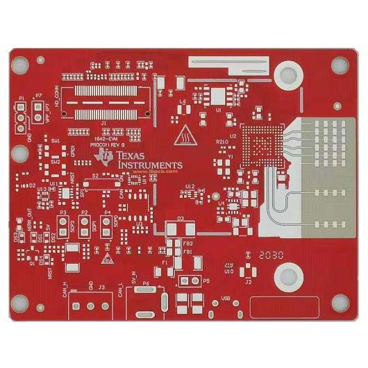
3. There are several reasons for the widespread use of copper: 1) EMC (Electromagnetic Compatibility). For extensive areas of ground or power supply, copper provides shielding, and in specific areas, such as PGND for protection. 2) PCB Manufacturing Process. Copper is used on PCB layers to minimize the impact of electroplating and lamination deformation on small traces. 3) Integrity Marking. This ensures a complete path for high-frequency digital signals and reduces routing within the DC network. Additionally, copper helps with heat dissipation and the installation of specialized equipment. Copper layers are utilized for various purposes.
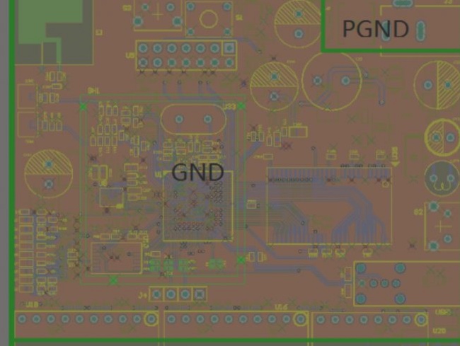
a. **EMC Considerations**: For extensive areas of land or air supply, appropriate shielding is necessary, including specific protection for areas such as PGND.
b. **PCB Processing Requirements**: The copper fuse PCB is situated on the floor, with minimal wiring to avoid impacts from electroplating and lamination deformation.
c. **Signal Integrity**: To meet signal integrity requirements, provide a complete return path for high-frequency digital signals and minimize the wiring for the DC network. Additionally, considerations such as heat dissipation and special device installations may necessitate the use of copper.
1. One of the main advantages of copper plating is the reduction of soil resistance (many so-called antifouling agents also work by reducing soil resistance). Digital circuits, which generate substantial spike currents, require further reduction in ground impedance. It is generally accepted that circuits with digital devices need a larger ground area. In contrast, analog circuits with copper coating can form ground loops that cause electromagnetic coupling and interference, especially if it exceeds the gain (excluding high-frequency circuits). Therefore, not all circuits require standard copper. Notably, copper mesh provides better shielding than solid copper blocks.
2. The significance of copper circuits is evident in the following areas: 1. Connecting copper paths to the ground wire helps reduce the loop area. 2. Spreading a large area of copper lowers the resistance of the ground wire and minimizes the voltage drop between points. This means that both digital and analog grounds benefit from added copper to enhance anti-interference capability. At high frequencies, it is crucial to separate digital and analog grounds, spread the copper, and then connect them at a single point. Before connecting, this single point can be wound with a wire around a magnetic ring. However, if the frequency is not excessively high or the equipment operates optimally, this step can be simplified. Crystal oscillators, considered high-frequency radiation sources, should be surrounded by copper, with their housings polished to reduce interference.
3. The distinction between a copper block and a grid involves three main functions: 1. Aesthetic appeal 2. Noise reduction 3. Mitigation of high-frequency interference according to wiring standards. Power and ground layers should be as extensive as possible. Adding a grid may seem counterintuitive, particularly at high frequencies where sharp effects are also undesirable. If the power plane exceeds 90 degrees, numerous issues may arise. Proper handling is crucial, as inconsistent hand-painted soldering can lead to problems. The image you see likely indicates an issue from wave soldering techniques requiring localized heating. Variations in heat transfer coefficients can lead to scattered copper and board deformation, resulting in defects. The tip pin on the top steel cover also requires precise processing. Mistakes are common, and error rates can increase. Although current etching processes facilitate film adhesion, strong acid projects might not fully corrode and may leave residues. If the board is damaged, chips could be compromised. The angle of drawing is essential for consistent product quality. In some cases, surface devices may not be classified. Product consistency depends on two scenarios: 1. Effective corrosion processing 2. Reflow soldering instead of wave soldering, though this significantly increases assembly line costs by 3-5 times.

