Printing, Mounting, and Reflow Soldering of Flexible PCBs
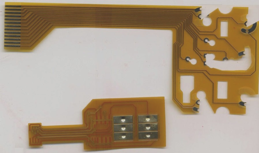
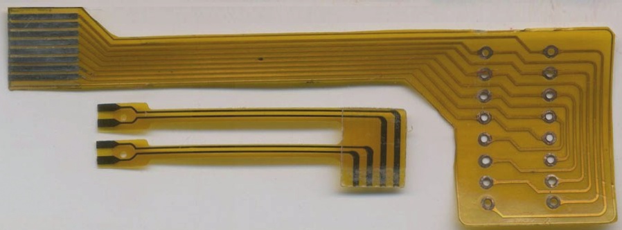
When working with Flexible Printed Circuit boards (FPC), it is crucial to ensure proper printing, mounting, and reflow soldering processes. Unlike rigid circuit boards, FPCs require specific considerations due to their soft characteristics.
Printing Process
- Fix the FPC securely on the carrier board before printing to prevent movement.
- Use a flexible stencil that can adapt to the soft nature of FPC.
- Control the stencil thickness to ensure even and accurate solder paste application on FPC pads.
Mounting Components
- Avoid applying excessive force during component placement to prevent FPC deformation.
- After mounting, undergo reflow soldering with controlled heating rates and temperature curves to prevent FPC warping.
Production Process of FPC
For Surface Mount Technology (SMT) points of FPC, using silicone plates or magnetic fixtures for fixation can simplify the process. It is essential to fix the FPC accurately on the carrier board before SMT.
Fixation Methods
- Single-sided tape fixation: Use thin, high-temperature resistant tape to prevent FPC deviation or warping.
- Double-sided tape fixation: Stick FPC to the carrier board with attention to tape viscosity to avoid tearing.
Solder Paste Printing
Ensure the solder paste has excellent thixotropy for easy printing and firm adhesion to FPC surfaces without defects.

Optimizing FPC Manufacturing Process for Improved Quality
- When loading FPC on the carrier board, the use of high-temperature resistant adhesive tape can lead to inconsistencies in flatness. This affects the printed surface of FPC, making it less flat and uniform compared to PCBs.
- For optimal results, avoid using a metal scraper and opt for a polyurethane scraper with a hardness of 80-90 degrees. It is recommended to have an optical positioning system in the solder paste printing machine to maintain printing quality.
- Equipment parameter settings play a crucial role in achieving the desired printing effect due to the small gaps that exist between FPC and the carrier board.
- Ensure cleanliness at the printing station to prevent FPC contamination. Regularly wiping the steel mesh and protecting the gold fingers and gold-plated buttons from solder paste contamination is essential.
- For FPC surface mount technology (SMT), consider using medium to high-speed mounting machines based on product characteristics and component quantity. Opt for accurate settings in suction nozzle height, blowing pressure, and movement speed due to the uneven surface of FPC.
- Reflow soldering of FPC requires the use of a hot air convection infrared reflow soldering furnace to ensure even temperature distribution and reduce welding defects. Proper temperature curve testing and setting are crucial for soldering quality.
- During temperature curve testing, pay attention to the heat absorption properties of the carrier plate and components on the FPC. Setting the temperature curve accurately can significantly impact soldering quality.
- For furnace temperature debugging, use temperature curve pipelines for better control of parameters in each temperature zone. Adjust the furnace temperature based on solder paste technology requirements and ensure stable reflow furnace operation.
- During inspection, testing, and removal of FPC from the carrier board, consider adding a forced cooling fan at the outlet to aid in quick cooling. Handle the FPC with care to prevent tearing or creases, especially when the plates are still hot.
Inspecting and Testing Flexible Printed Circuits (FPC)
When removing FPC, it is crucial to visually inspect it under a magnifying glass of 5 times or more. Focus on checking for surface residue, discoloration, tin on gold fingers, solder beads, IC pin solder joints, and solder connections. Due to the surface of FPC not being very flat, AOI inspection may lead to high misjudgment rates. However, specialized testing fixtures can enable FPC to undergo ICT and FCT testing.
For ICT and FCT testing on FPC connected boards, board splitting may be necessary. While blades and scissors can be used for board splitting, this method may result in lower work efficiency and quality. For large-scale production of irregular FPC, specialized FPC stamping and dividing molds can greatly improve work efficiency. The neat and beautiful edges of the punched-out FPC can effectively prevent solder joint cracking.
Assembly and Welding of PCBA Flexible Electronics
Precise positioning and fixation of FPC are key in the assembly and welding process of PCBA flexible electronics. Making suitable carrier plates is essential for good fixation. The process involves pre-baking, printing, SMT, and reflow soldering of FPC. The SMT process difficulty of FPC is higher than that of PCB hard boards, necessitating precise setting of process parameters and strict production process management.

Line engineers and IPQC should conduct thorough inspections, promptly detect abnormalities, analyze root causes, and implement necessary measures to keep the defect rate of FPC SMT production line within dozens of PPMs.
PCBA Production Equipment
The essential equipment for PCBA production includes solder paste printing machines, SMT machines, reflow soldering, AOI detectors, component trimming machines, wave soldering, tin furnaces, washing machines, ICT testing fixtures, FCT testing fixtures, and aging testing racks.
Solder Paste Printing Machine
Modern solder paste printing machines consist of plate loading, solder paste addition, embossing, and circuit board feeding mechanisms. The machine leaks solder paste onto solder pads through the steel mesh, enabling automatic SMT after fixing the circuit board on the printing positioning table.
SMT Machine
The SMT machine accurately places surface-mounted components on PCB pads by moving the mounting head. It comes in manual and fully automatic types.
Reflow Soldering
Reflow soldering heats air or nitrogen to a high temperature, allowing the solder on components to melt and bond with the motherboard. This process offers temperature control, avoids oxidation, and is cost-effective.
AOI Detector
AOI (Automatic Optical Inspection) detects common defects in welding production by scanning the PCB through a camera, comparing images with qualified parameters in the database, and displaying defects for repair.
Component Trimming Machine
Used for trimming and deforming pin components.
Wave Soldering
Wave soldering involves contacting the welding surface with high-temperature liquid tin to achieve the welding purpose. The liquid tin forms waves and ensures efficient soldering.
Tin Furnace
Advanced PCB Testing and Manufacturing Solutions
- Tin Furnace: The tin furnace, commonly used in electronic welding, ensures excellent welding consistency for discrete component circuit boards. It offers convenient operation, speed, and high work efficiency.
- Plate Washer: This tool is essential for cleaning PCBA boards and effectively removes residue from welded boards.
- ICT Testing Fixtures: ICTTest is utilized to assess open circuits, short circuits, and welding conditions of all PCBA circuit components. It tests the test points formed by the probe and PCBlalayout contact.
- FCT Testing Fixture: FCT (Functional Testing) involves creating a simulated operational environment for the UnitUnderTest (UUT) board to evaluate its functionality under various design states. It verifies the UUT’s performance by applying appropriate excitation and checking the output response.
- Aging Test Frame: The aging test bench conducts batch testing on PCBA boards, simulating extended user operations to identify any issues with the boards.
WellCircuits boasts a sophisticated SMT factory, PCB, and FPC factory, offering comprehensive OEM services for PCBA and FPC. Their products cater to diverse industries such as automotive electronics, medical equipment, industrial control, aerospace, and communication equipment.

