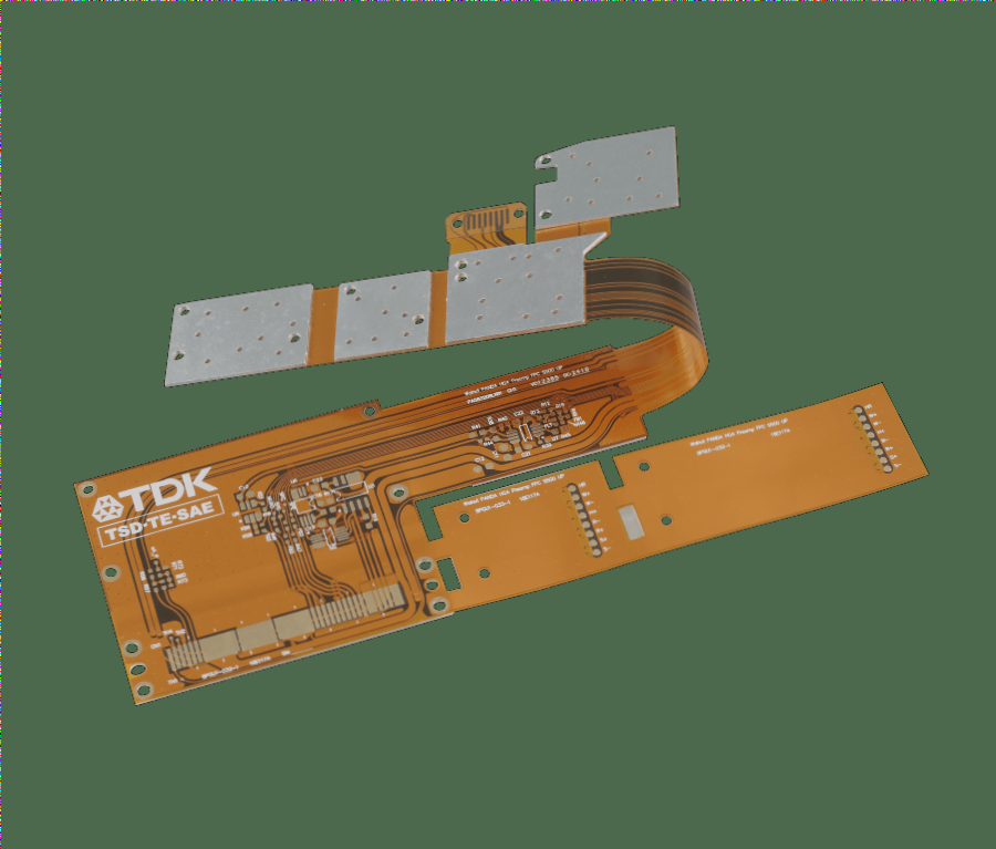
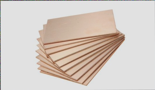
2. Battery FPCs are generally 1 to 2 layers, with multi-layer FPCs being relatively uncommon. The base material and cover layer of flex PCBs are typically made from polyimide, where the substrate and copper foil are pressed together.
3. The thickness of some FPCs is denoted by the thickness of the copper foil, such as 1.5oz or 2.0oz.
4. Unlike PCBs, the openings of the cover layer on the copper foil in FPCs are generally smaller than the area of the copper foil itself. In contrast, the area of the solder mask on PCBs is typically larger than the area of the copper foil.
5. It’s important to note that the FPC substrate and copper foil are bonded with resin. In some instances, resin may spill over, leading to pad contamination and solder leakage.

Certainly! Here’s a revised version of your text:
Because flexible circuit boards (FPCs) exhibit poorer flatness compared to traditional PCBs, various factors such as support and tape complicate the complete adhesion of FPCs to the screen board during the printing process, potentially leading to issues in solder paste control.
Based on practical experience, two recommendations are suggested for stencil design: Firstly, for IC components with dense pins, it is advisable to narrow and elongate the mesh of the stencil as much as possible. Thinner stencils, particularly those featuring an inverted trapezoidal mesh, have proven more effective for printing. Secondly, for sheet components or connectors with a larger span, enlarging the stencil mesh helps prevent soldering defects caused by uneven FPCs.
Given that battery FPCs require support, the reflow oven’s profile must account for heat absorption by the support plate during soldering. Typically, it is recommended to set the temperature below the reflow oven slightly higher than the hot zone above, ensuring similar temperatures between the support plate and FPC to prevent cold welding. Additionally, robust cooling air at the oven outlet ensures the support plate rapidly reaches a safe temperature. Consideration can also be given to incorporating a cooling fan at the outlet for further control.

In order to ensure the flatness of the flexible circuit board, manufacturers typically flatten the battery flexible circuit board before shipment. Due to the flexibility of FPCs, vacuum packaging is impractical. Therefore, during transmission and use, it is crucial to maintain the flatness of the FPC and minimize bending.
FPCs are supported throughout the SMT process, often using non-heat-resistant and anti-static synthetic materials. Some companies employ thin aluminum sheets for support. A common method for positioning involves using high-temperature tape to attach the FPC to the support plate.
However, it’s important to place the tape at the midpoint of the four corners and along the longer sides of the FPC to prevent the battery flexible circuit board from warping. Moreover, the thickness of the tape can affect solder paste printing. Therefore, avoid positioning the tape near densely packed components, components with thin pins, or over the pads. More attention should be given to ensure that the tape does not adhere to the pads.
1. In order to facilitate separation, the FPC and the edge are generally pre-cut along the contour. The uncut part typically retains a layer of substrate (Micro Joint) and requires a stamp hole to be made on it. This not only facilitates division but also prevents large burrs at the splitting point.
2. The connection part also ensures that the flexible circuit board does not warp during the SMT process, so the Micro Joint should be maintained at each incision in the FPC. Flex PCB cutting can be done manually or using a special die similar to a punching machine.


