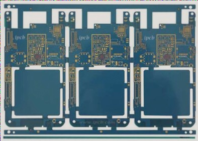
1. The PCB breakout board is a specialized motherboard primarily designed for Industrial PCs to assist with industrial projects.
2. It can be used with high-level, low-level, or other control modes depending on your needs.
3. Choose whether a fully isolated breakout board is necessary based on your specific requirements.

### Breakout Board Overview
The primary function of the breakout board is to convert the rotational motion of the motor into linear motion. Relay modules often utilize ball screws or grinding screws. The rolling friction between the ball screw and the nut is mediated by steel balls, which enable smooth movement, high transmission efficiency, and easy high-speed operation. Adjusting the diameter of the steel balls or using double nuts can effectively address axial clearance issues.
### PCB Breakout Board Structure
The PCB breakout board is positioned between the components and the circuit board, featuring metal rewiring (RDL) on both the upper and lower surfaces. After packaging, components are generally connected to the adapter board through flip soldering, while the breakout board interfaces with the PCB below via BGA at the board level. The PCB breakout board acts as an intermediary bridge, facilitating interconnection among multiple chips through RDL, and between chip components and circuit boards.
### Advantages of Breakout Boards
1. **High-Density I/O Interconnection**: As interconnect density and I/O quantity increase, the pitch of metal protrusions for flip-flop welding decreases, leading to higher production costs and manufacturing challenges. The breakout board utilizes RDL layers with small linewidth and high-density wiring to redistribute high-density I/O, minimizing the need for pitch bumps. TSV-based breakout boards can efficiently manage high-density I/O on the board’s rear side, shortening interconnection lengths between chips and circuit boards, thus reducing power consumption and latency.
2. **Improved Integration**: The small RDL line width and high wiring density on the breakout board enhance system integration. Although the system area may be larger compared to 3D integration, the PCB breakout board can improve integration and reduce the system area compared to traditional wire bonding methods.
3. **Heterogeneous Integration**: Breakout boards can encapsulate chips with varying functions, processes, and substrates, enabling heterogeneous system integration and expanding functionality.
### Classification of Breakout Boards
Breakout boards can be categorized based on material into inorganic and organic types. Inorganic breakout boards include silicon, ceramic, and glass, while adapter boards can be classified as TSV or TSV-free based on the presence of TSV.
1. **Organic Breakout Boards**: These boards are cost-effective and have simpler manufacturing processes. However, they have a large coefficient of thermal expansion (CTE) and poor dimensional stability, which limits interconnect line width and I/O density. They also have low thermal conductivity and poor heat dissipation performance, and their small elastic modulus can lead to warping during manufacturing.
2. **Ceramic Breakout Boards**: These boards offer good dimensional stability, high thermal conductivity, and effective heat dissipation. However, their I/O density is limited, resulting in high manufacturing costs and complexity.
3. **Silicon Breakout Boards**: Silicon boards provide excellent dimensional stability, enabling small line widths, small pitches, and high-density wiring. However, they have high manufacturing costs and significant transmission loss at high frequencies.
4. **Glass Breakout Boards**: Glass boards offer good insulation and isolation, effectively reducing insertion loss and crosstalk at high frequencies. The thermal expansion coefficient of glass can be adjusted to reduce thermal mismatch with different materials. However, glass is brittle, has low thermal conductivity, poor heat dissipation, and challenges in manufacturing small aperture holes with large aspect ratios.
5. **Silicon-Based Breakout Boards with TSV**: These boards are gaining attention in high-end packaging. The RDL line width is less than 1µm, and TSV is 50:5, allowing for small line widths, small pitches, and high-density wiring. CoWoS (Chip on Wafer on Substrate) first introduced silicon-based breakout boards to commercial applications. HPC packages using TSV-based silicon breakout boards can integrate high-performance computing chips and memory chips into a single package, reducing power consumption by 50% and tripling performance.
6. **Organic Breakout Boards without TSV**: Typically, these boards have lower interconnection density and require local interconnection enhancements through embedded silicon bridges. Intel’s embedded multi-chip bridge (EMI B) is a prime example, utilizing a high-density RDL silicon breakout board embedded in an organic breakout board to connect multiple chips while reducing production costs. This technology is used in the i7-8809G, connecting the GPU and HBM via a silicon bridge.
The PCB breakout board is a specialized motherboard primarily used in industrial PCs to support industrial projects. Similar to commercial motherboards, it is a card-shaped composite board with various industrial components and sockets. Breakout boards are typically compact and feature multiple RS232 serial ports, RS485/422 ports, or LAN network ports. They use low-power chips to conserve energy and address issues related to high temperatures and prolonged operation.

