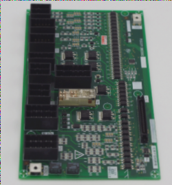
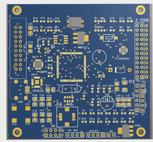
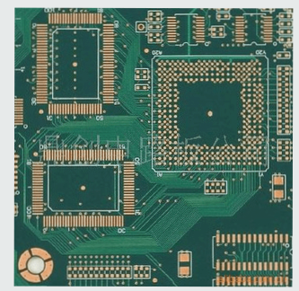
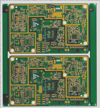
The ambient lighting source in the PCB lithography process is yellow light, rather than the red light typically used in traditional photography darkrooms. As a result, this process is commonly referred to as the “yellow light” process.
The yellow light process consists of several stages: PR (photoresist) coating, exposure, development, and etching, which together create the desired circuit pattern.
**FPC Yellow Light Process**
To prevent foreign particles from remaining on the copper surface, which could lead to poor PCB circuit formation, the process must be carefully controlled.
Increasing the roughness of the copper surface enhances the adhesion between the copper and the photosensitive film.
**Reaction Mechanism:**
Micro-etching bath solution: AD485 (Na2S2O8 + stabilizer), H2SO4
Na2S2O8 + Cu → Na2SO4 + CuSO4
CuO + H2SO4 → CuSO4 + H2O
**Concentration Control:**
AD485: 50-80g/L
Cu2+: 10g/L
**Photosensitive Film Lamination**
A photosensitive film is applied to the substrate in preparation for the circuit formation. The composition of the photosensitive film and its process include:
**Hot Pressing and Rolling Effect:**
The photosensitive film and the substrate are firmly bonded under heat and pressure. The pressing temperature is typically 100-110°C, with a pressure of 0.3 MPa.
**Vacuum Chamber Function:**
The vacuum chamber helps to prevent the formation of foreign particles or bubbles within the photosensitive film. The vacuum pressure is maintained between 95 and 105.
**High-Precision Exposure (Exposure):**

**The UV light is irradiated on the photosensitive film to form the circuit pattern through a specified glass mask, which cures the exposed areas.**
**Process Flow:**
– **Illustration:**
The exposed version of the GLASS MASK is divided into large and small boards, and the corresponding exposure machines differ accordingly.
By controlling the development time, the development can be performed using a mild alkaline developer.
**Mechanism:**
– The exposed areas of the (positive) photoresist quickly dissolve in the developer, while the unexposed areas dissolve more slowly.
For negative photoresist, the opposite occurs: the exposed areas dissolve slowly in the developer, while the unexposed areas dissolve more quickly. A commonly used developer is sodium carbonate, at a concentration of 6.5-7.0g/L.
**Etching:**
– Copper is dissolved using an etching solution (such as ferric chloride, copper chloride, etc.).
**Etching Factor:**
– During the etching process, the etching solution not only etches in the horizontal directions but also vertically, resulting in inevitable side etching. The ratio of side etching width to etching depth is called the etching factor. Complete elimination of side etching is not currently possible in the industry, but it can be minimized. This is typically achieved by adjusting parameters such as pressure, speed, and temperature to control side erosion.
**Tailun FPC Protective Film Introduction:**
– **High-Temperature Bearing Film:**
This film is used in the Panel-to-Panel process. For PCB single-sided boards, dry film is applied to the copper surface, while a carrier film is applied to the PI surface.
– **Repost Film:**
Small auxiliary materials used for reapplication, primarily for small-area needs. This includes cover films, reinforcement materials, shielding films, and other pressure-sensitive materials. These materials significantly improve processing efficiency and product yield.
– **Die-Cut Load-Bearing Film:**
Before shaping the FPC, it is first adhered to a PET film with weak adhesion. Then, partial cutting (or embedded punching) is performed using a die. This allows the FPC to remain intact for the user, who can either assemble the components first or remove the FPC from the PET film after assembly is complete.
– **Shipment Protective Film:**
A surface protection material designed to prevent damage to the FPC. It uses PET with a certain stiffness as the base material, meeting various viscosity requirements. This product series includes surface protection materials.
The PCB is packaged with double-layer PET film. The sticky side of the film is fixed to a table, with products neatly arranged on the adhesive side. After full adhesion, a release film is applied and smoothed by hand. The stack is then wrapped, with FR2 partitions placed on the top and bottom for stability. The package is sealed in a plastic bag, labeled appropriately, and prepared for storage.
If you have any PCB manufacturing needs, please do not hesitate to contact me.Contact me
The yellow light process consists of several stages: PR (photoresist) coating, exposure, development, and etching, which together create the desired circuit pattern.
**FPC Yellow Light Process**
To prevent foreign particles from remaining on the copper surface, which could lead to poor PCB circuit formation, the process must be carefully controlled.
Increasing the roughness of the copper surface enhances the adhesion between the copper and the photosensitive film.
**Reaction Mechanism:**
Micro-etching bath solution: AD485 (Na2S2O8 + stabilizer), H2SO4
Na2S2O8 + Cu → Na2SO4 + CuSO4
CuO + H2SO4 → CuSO4 + H2O
**Concentration Control:**
AD485: 50-80g/L
Cu2+: 10g/L
**Photosensitive Film Lamination**
A photosensitive film is applied to the substrate in preparation for the circuit formation. The composition of the photosensitive film and its process include:
**Hot Pressing and Rolling Effect:**
The photosensitive film and the substrate are firmly bonded under heat and pressure. The pressing temperature is typically 100-110°C, with a pressure of 0.3 MPa.
**Vacuum Chamber Function:**
The vacuum chamber helps to prevent the formation of foreign particles or bubbles within the photosensitive film. The vacuum pressure is maintained between 95 and 105.
**High-Precision Exposure (Exposure):**
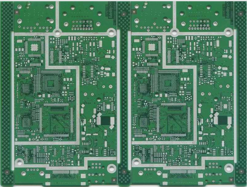
**The UV light is irradiated on the photosensitive film to form the circuit pattern through a specified glass mask, which cures the exposed areas.**
**Process Flow:**
– **Illustration:**
The exposed version of the GLASS MASK is divided into large and small boards, and the corresponding exposure machines differ accordingly.
By controlling the development time, the development can be performed using a mild alkaline developer.
**Mechanism:**
– The exposed areas of the (positive) photoresist quickly dissolve in the developer, while the unexposed areas dissolve more slowly.
For negative photoresist, the opposite occurs: the exposed areas dissolve slowly in the developer, while the unexposed areas dissolve more quickly. A commonly used developer is sodium carbonate, at a concentration of 6.5-7.0g/L.
**Etching:**
– Copper is dissolved using an etching solution (such as ferric chloride, copper chloride, etc.).
**Etching Factor:**
– During the etching process, the etching solution not only etches in the horizontal directions but also vertically, resulting in inevitable side etching. The ratio of side etching width to etching depth is called the etching factor. Complete elimination of side etching is not currently possible in the industry, but it can be minimized. This is typically achieved by adjusting parameters such as pressure, speed, and temperature to control side erosion.
**Tailun FPC Protective Film Introduction:**
– **High-Temperature Bearing Film:**
This film is used in the Panel-to-Panel process. For PCB single-sided boards, dry film is applied to the copper surface, while a carrier film is applied to the PI surface.
– **Repost Film:**
Small auxiliary materials used for reapplication, primarily for small-area needs. This includes cover films, reinforcement materials, shielding films, and other pressure-sensitive materials. These materials significantly improve processing efficiency and product yield.
– **Die-Cut Load-Bearing Film:**
Before shaping the FPC, it is first adhered to a PET film with weak adhesion. Then, partial cutting (or embedded punching) is performed using a die. This allows the FPC to remain intact for the user, who can either assemble the components first or remove the FPC from the PET film after assembly is complete.
– **Shipment Protective Film:**
A surface protection material designed to prevent damage to the FPC. It uses PET with a certain stiffness as the base material, meeting various viscosity requirements. This product series includes surface protection materials.
The PCB is packaged with double-layer PET film. The sticky side of the film is fixed to a table, with products neatly arranged on the adhesive side. After full adhesion, a release film is applied and smoothed by hand. The stack is then wrapped, with FR2 partitions placed on the top and bottom for stability. The package is sealed in a plastic bag, labeled appropriately, and prepared for storage.
If you have any PCB manufacturing needs, please do not hesitate to contact me.Contact me

