A. Conventional SMD Placement
Features: The placement accuracy is relatively low, with a limited number of components. The primary components are typically resistors and capacitors, along with a few specialized shapes.
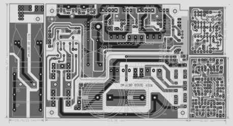
**Key Process:**
1. **Solder Paste Printing:** The FPC is positioned on a specialized printing pallet based on its appearance. Typically, a small semi-automatic printing machine is used, although manual printing can be employed; however, manual methods generally yield lower quality compared to semi-automatic processes.
2. **Placement:** Manual placement is commonly utilized, with certain components requiring higher positioning accuracy that can be achieved through a manual placement machine.
3. **Welding:** Reflow soldering is primarily used, though spot welding may be applicable in specific scenarios.
**2. High-Precision Placement**
**Features:** The FPC must have a MARK mark for substrate positioning, and it needs to be flat. Securing the FPC can be challenging, making it difficult to ensure consistency in mass production, thus demanding high-quality equipment. Furthermore, controlling the solder paste printing and placement processes is quite complex.
**The Key Process:**
1. **FPC Fixation:** From the printing phase to reflow soldering, the entire process is anchored on the pallet. The pallet should have a low thermal expansion coefficient. Two fixation methods are employed: Method A for QFP lead spacing greater than 0.65mm, and Method B for spacing less than 0.65mm.
– **Method A:** The pallet is positioned on a template, with the FPC secured to the pallet using a thin, high-temperature-resistant tape. This tape should have moderate adhesion, allowing easy removal post-reflow without leaving any residue on the FPC.
– **Method B:** The pallet is custom-made, designed to endure multiple thermal cycles with minimal deformation. It includes a T-shaped positioning pin, which is slightly taller than the FPC.
2. **Solder Paste Printing:** Since the pallet holds the FPC, the height is inconsistent with the pallet’s surface due to the positioning tape, necessitating the use of an elastic scraper during printing. The composition of the solder paste significantly affects the printing outcome, making the selection of suitable solder paste crucial. Additionally, the printing template for Method B requires special processing.
3. **Mounting Equipment:** Initially, the solder paste printing machine must feature an optical positioning system to ensure welding quality. While the FPC is fixed on the pallet, tiny gaps may exist between them, distinguishing it from traditional PCB substrates. Consequently, the calibration of equipment parameters significantly impacts the printing quality, placement accuracy, and welding results, thereby imposing strict requirements on process control for FPC placement.

