You can now place orders directly through the Wellcircuits Plugin for KiCad
Once your PCB design is complete in KiCad, the final step is to generate the Gerber and drill files, which will then be sent to the PCB manufacturers for production. This guide uses the demo project provided with KiCad. All steps have been tested with KiCad version 7.0.0; however, there might be slight differences if you’re using a different version of KiCad.
Generating Gerber Files
Tip: To avoid potential manufacturing issues, it is highly recommended to perform a DRC (Design Rule Check) before exporting the Gerber files.
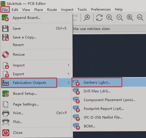
Open the PCB file with the .kicad_pcb extension, then click on “File” → “Fabrication Outputs” → “Gerbers (.gbr)…” as shown in the image below.
After clicking, the Gerber setup window will appear, as shown in the image below. Please refer to this image for the correct settings.
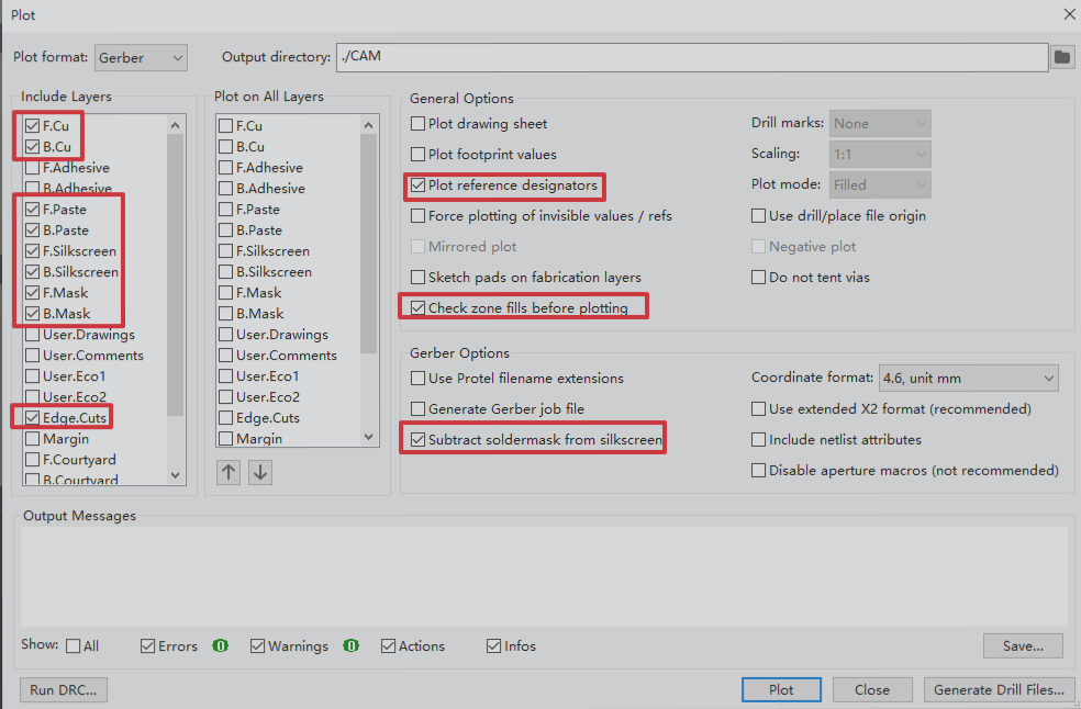
Next, click the “Plot” button at the bottom of the window. The generated Gerber files will be saved to the target folder you specified earlier.
If there are any expired zone fills and you forgot to refill them, KiCad will prompt you for confirmation once you check the “Check zone fills before plotting” option. Simply click “Refill,” and the file generation process will continue.

Generating Drill Files
In the Gerber generation window, click on “Generate Drill Files…” located in the bottom-right corner. This will open the Drill file settings window, as shown in the image below. Please refer to the image for the correct settings.
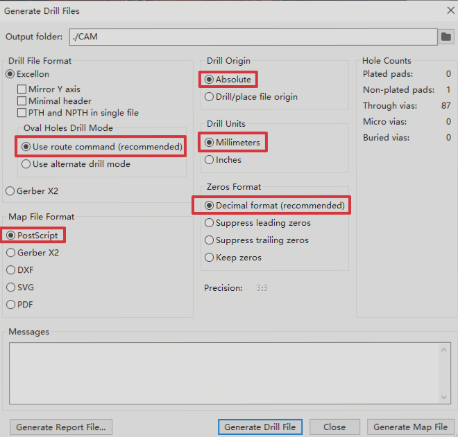
Then, click the “Generate Drill Files” button at the bottom of the window. The generated Drill files will be saved in the target folder you specified earlier.
At this point, the export of Gerber and Drill files is complete. By default, these files are usually placed in a folder named “CAM” within the directory where your PCB file is located. You can find the Gerber files in this folder, as shown in the image below.

If you have any questions about PCBs or PCBA, please feel free to contact us at info@wellcircuits.com

