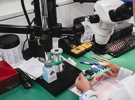
Definition of Ground Wire
In PCB layout design, a ground wire serves as the reference point for circuit potential. While traditionally seen as an equipotential body, the reality is that potential variations exist along the ground wire, leading to circuit malfunctions. HENRY offers a practical definition, describing the ground wire as a low-impedance pathway for signals to return to the source, emphasizing current flow within the wire.
The Impedance of the Ground Wire
Despite measuring low resistance in the milliohm range, the impedance of the ground wire can cause significant voltage drops when current flows through, potentially resulting in abnormal circuit behavior.
Ground Interference Mechanism

Common Impedance Interference
Shared ground wires between circuits can lead to common impedance coupling, where the ground potential of one circuit is affected by the working current of another due to impedance. In digital circuits, higher frequency signals can amplify this issue.
Ground Interference Countermeasures
Ground Loop Mitigation in PCB Design
To combat ground loop interference, reducing current in the loop is key. Strategies include floating equipment at one end to interrupt the ground loop, employing transformers for device connection to sever ground loop current, and utilizing optical isolation to eliminate ground loops.
Optical Isolators for Ground Loop Interference
- Optical isolators are an effective solution for dealing with ground loop interference.
- Two common optical connection methods are optocoupler devices and optical fiber connections.
- Optocouplers have around 2pF of parasitic capacitance, providing good isolation at high frequencies.
- Optical fiber, on the other hand, has negligible parasitic capacitance but may be less convenient and cost-effective compared to optocouplers.
Using Common Mode Chokes on Connecting Cables
- Common mode chokes can help increase the impedance of ground loops, reducing circuit current under specific ground voltages.
- It’s crucial to manage the parasitic capacitance of common mode chokes to maintain their effectiveness against high-frequency interference.
- More turns in a common mode choke can lead to higher parasitic capacitance, potentially impacting high-frequency isolation.
Eliminating Common Impedance Coupling
- There are two main methods to eliminate common impedance coupling.
- Reducing the impedance of the common ground wire can lower the voltage on the common ground, helping to control common impedance coupling.
- Preventing circuits prone to interference from sharing a common ground through proper grounding practices is another effective approach.
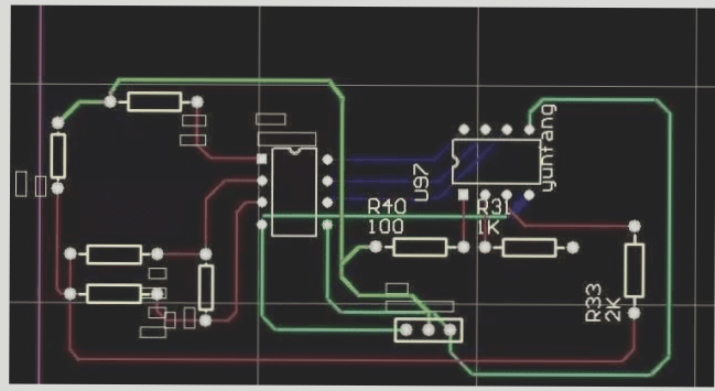
- Minimizing ground wire impedance by using flat or multiple parallel conductors can help reduce interference.
- Implementing a ground wire grid on printed circuit boards or using dedicated ground layers in multilayer boards can also lower impedance.
- Parallel single-point grounding is a recommended technique to avoid common impedance coupling.
- Series single-point grounding can be used for circuits with less mutual interference, categorizing circuits based on signal strength and type.