Designing Irregularly Shaped PCB Boards
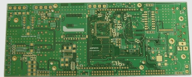
Most PCB boards are rectangular in shape, but some designs require irregular shapes, which can be challenging to create. This article explores how to design irregularly shaped PCB boards.
Managing Complex PCB Shapes
As PCB boards shrink in size to accommodate more functions and higher speeds, managing complex shapes becomes crucial. Designers face challenges when fitting boards into enclosures with height constraints, as typical EDA tools lack mechanical CAD capabilities.
Integration of Non-Rectangular PCBs
Despite the emphasis on compactness in consumer electronics, functionality often demands non-rectangular shapes. Devices like smartphones and tablets showcase the need for unconventional PCB shapes.
Importing Mechanical Specifications
Integrating precise mechanical engineering specifications into PCB design tools is essential. Formats like DXF, IDF, and ProSTEP facilitate data transfer between mechanical drawings and PCB layout software, streamlining the process and minimizing errors.
Graphics Interchange Format – DXF
DXF is widely used for exchanging two-dimensional data between mechanical and PCB design domains. Most PCB tool suppliers support DXF, simplifying data exchange. The IDF format enhances 3D visualization of PCB boards and component information transfer.
STEP and ProSTEP
- STEP format improves 3D data transmission by modeling components in intricate detail beyond simple shapes.
- ProSTEP enhances STEP file exchange to address challenges in tracking changes between board and component information.
Benefits of ProSTEP in PCB Design
- ProSTEP offers improvements over IDF and STEP formats
- Enables change tracking and supports original system work
- Facilitates reviewing changes post-baseline establishment
- Allows PCB and mechanical engineers to scrutinize and approve layout modifications
- Supports board outline adjustments and alternative component placements
Enhanced Communication with ProSTEP
- Streamlined communication fosters Engineering Change Orders (ECOs)
- Facilitates collaboration between ECAD and mechanical teams
- Most ECAD and mechanical CAD systems now support ProSTEP
- Enhances communication, saves time, and reduces errors in designs
Time-Saving Features
- Engineers can define detailed board profiles and constraints electronically
- Prevents misinterpretation of board dimensions
Recommendation
If you haven’t utilized DXF, IDF, STEP, or ProSTEP formats for data exchange, exploring their potential benefits is advisable. Leveraging electronic data interchange can prevent redundant efforts in recreating complex PCB profiles.


