Building Your Own Arduboy: A Step-by-Step Guide
-
Hardware Components Used:
 Arduino Micro & Genuino Micro
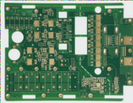
- One PCB board from Wellcircuits
 Arduino Micro & Genuino Micro
Story Behind the Project:
A few months ago, I stumbled upon Arduboy, a miniature 8-bit game platform designed for learning, sharing, and playing games online. Built around the ATmega32u4 microcontroller, similar to the one in Arduino Pro Micro, Arduboy allows users to create their own games. Inspired by this, I decided to fabricate the hardware part on a PCB board, and it was a success!
While I enjoyed playing retro games, the messy breadboard setup prompted me to explore professional PCB designing. This project focuses solely on PCB design, offering a perfect opportunity to delve into this area. Join me as we create our version of Arduboy, from circuit diagram to circuit board!
Let’s dive in!
Step 1: Things You Will Need
- 1x Arduino Pro Micro (5V)
- 1x OLED Display (SPI)
- 6x Tactile Push Button
- 1x Piezo Speaker
- 1x Common Anode RGB LED
Step 2: Testing on a Breadboard

On the breadboard, connect all the required components as per the circuit diagram provided. Follow the connections guide to ensure everything is set up correctly.
Control Keys:
- UP – A0
- DOWN – A3
- RIGHT – A1
- LEFT – A2
- A – D7
- B – D8
OLED Display:
- SCL – D15
- SDA – D16
- DC – D4
- RES – D2
Speaker:
- SPEAKER + – D5
- SPEAKER – – D6
RGB LED:
- RED – D10
- GREEN – D3
- BLUE – D9
Step 3: Uploading Games to Arduino
Before uploading any games to Arduino, make sure to follow these steps:
Designing PCB in PCB Design Software
Learn how to design your PCB using Arduino IDE:
-
Open Arduino IDE
-
Go to File > Preferences
-
Copy and paste the URL below in Additional Boards Manager URL text box and click on OK.
-
Go to Tools > Boards > Boards Manager
-
In the text box type “homemade” or “Arduboy homemade”
-
Select Arduboy Homemade package and click Install
After installing the library, go to Tools menu and make the following selections:
-
Board: Homemade Arduboy
-
Bootloader: Cathy3K
-
Based on: SparkFun Pro Micro 5V – Alternate Wiring
-
Core: Arduboy optimized core
-
Display: SSD1306
Open up the .ino file and hit upload.
Step 4: Designing PCB in PCB design software
Discover the latest PCB design software for your projects:

Step 5: Assembling Your PCB
Find out how to assemble your PCB like a pro:
Wellcircuits PCB Project
- Order your PCBs from Wellcircuits for high-quality results.
- Get all the necessary components from DIGKEY to save on shipping costs.
- Prepare your circuit diagram and start soldering the components following the silkscreen markings.
- When soldering SMD components, use plenty of flux for easier soldering of tiny pins.
- Even if it’s your first time soldering SMD components, with the right techniques, the soldering job can turn out well.
Check out the image of a PCB project completed with components sourced from Wellcircuits: