The Versatile SAMD21E18 Microcontroller for Cost-Effective Designs
The SAMD21E18, part of the SAMD21 series, is a powerful Cortex M0 microcontroller from Microchip. This variant offers up to 256 capacitive touch channels, built-in USB support, and solid performance for various applications.
Key Features of SAMD21E18:
- 32 pins, including up to 26 I/O pins
- Up to 256KB of Flash memory and 32KB of RAM
- Operates at a 3.3V logic level
- Available in TQFP32 and VQFN32 packages
Design Considerations:
The SAMD21E18, competitively priced, offers the highest RAM and Flash options in the E series. However, it is not 5V tolerant, requiring caution when interfacing with 5V systems to avoid damage.
Minimal Design Schematic:

The design includes a USB-C connector with resistors for standard USB-C protocol and protection diodes for power supply.
Power Management:
To safely power the board, a 5V to 3.3V step-down is crucial. The design utilizes an AP2112K-3.3V voltage regulator with decoupling capacitors for stable operation.
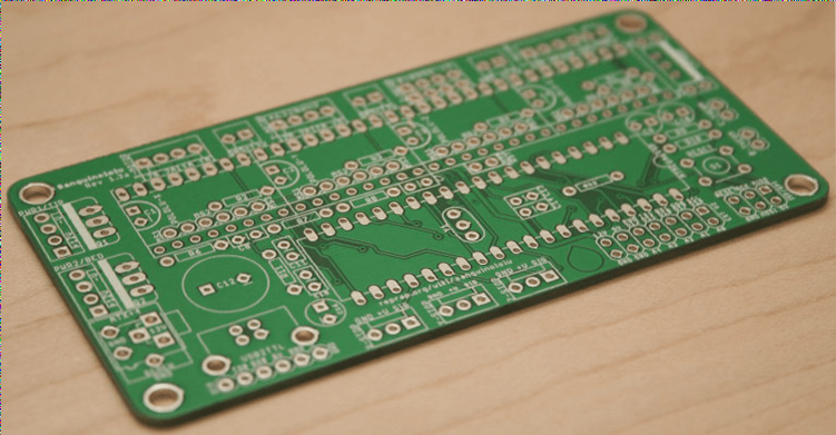
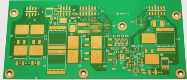
Routing and Assembly:
Thanks to the low component count, routing and assembly of this design are straightforward, as shown in the routed version below:

Exploring Design Options:
The SAMD21 series, especially the E18 variant, offers flexibility in Flash and RAM sizes, package options, and cost-effective prototyping solutions. Wellcircuits provides affordable PCB prototyping services, making it easy to bring your designs to life.
Connect with Us:
For more designs and assistance, visit our GitHub repository. Feel free to reach out on Twitter (@rpitechguy) or via email at info@wellcircuits.com for any inquiries.