Types of PCB Circuit Diagrams
-
Schematic Diagram
The schematic diagram, also known as an “electrical schematic diagram,” illustrates the structure and operational principles of electronic circuits. It is crucial for circuit design and analysis, providing insight into component symbols and their interconnections.
-
Block Diagram
A block diagram uses blocks and connecting lines to depict circuit composition and working principles. Unlike a detailed schematic diagram, it categorizes the circuit into functional parts represented by boxes with brief text descriptions.
-
Assembly Drawing
An assembly drawing shows the physical appearance of circuit components for assembly. It guides beginners in connecting components to complete circuit assembly.
-
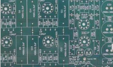
Printed Board Diagram
The printed circuit board diagram is used for assembling circuits on boards with metal foil layers on insulating substrates. These boards optimize component distribution and connections for circuit functionality.

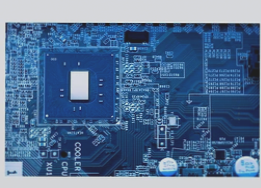
Printed circuit board manufacturing has advanced to include single-sided, double-sided, and multi-sided PCBs, catering to various sectors like daily life, industrial production, national defense, and aerospace. Understanding schematic diagrams is essential for mastering circuit principles, simplifying appliance design and repair.
If you require PCB manufacturing services, feel free to contact us.