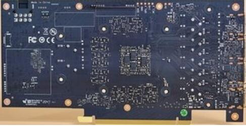
In the PCB design method based on signal integrity computer analysis, the most crucial aspect is the establishment of the PCB board-level signal integrity model, which differs from traditional design methods. The accuracy of the SI model will determine the correctness of the design, and the feasibility of creating the SI model will influence the practicality of this design method.
4.1. SI Model of PCB Design
Various models are available for PCB board-level signal integrity analysis in electronic design. Three of the most commonly used are SPICE, IBIS, and Verilog-A.
a. SPICE Model
SPICE is a powerful
1. General-purpose analog circuit simulators are essential tools in electronic design. The SPICE model has become widely utilized, with two primary versions: HSPICE and PSPICE. HSPICE is predominantly used for integrated circuit design, whereas PSPICE is more common in PCB board and system-level design.
2. The SPICE model comprises two components: Model Equations and Model Parameters. The provided model equations enable the SPICE model to integrate closely with the simulator’s algorithm, resulting in improved analysis efficiency and outcomes.
3. For signal integrity (SI) analysis at the PCB board level using the SPICE model, it is crucial for integrated circuit designers and manufacturers to supply a detailed and accurate description of the SPICE model for the integrated circuit I/O unit sub-circuit and the manufacturing parameters of semiconductor characteristics. Given that these materials often constitute intellectual property and confidentiality for designers and manufacturers, only a few semiconductor manufacturers offer corresponding SPICE models with their chip products.
4. The accuracy of the SPICE model’s analysis primarily depends on the source of the model parameters (i.e., data accuracy) and the applicability of the model equations. The combination of model equations with various digital simulators may also influence analysis accuracy. Additionally, the PCB board-level SPICE model involves significant simulation computations, making the analysis relatively time-consuming.
5. The IBIS model was initially developed by Intel Corporation for PCB board-level and system-level digital signal integrity analysis. It is now managed by the IBIS Open Forum and has become an official industry standard (EIA/ANSI 656-A).
6. The IBIS model describes digital integrated circuit I/O units and pins using I/V and V/T tables. Since the IBIS model does not require detailing the internal design of the I/O unit or transistor manufacturing parameters, it is widely supported by semiconductor manufacturers. Consequently, major digital integrated circuit manufacturers can now provide IBIS models along with their chips.
7. The accuracy of the IBIS model depends largely on the number of data points in the I/V and V/T tables and the precision of the data. Because PCB board-level simulations based on the IBIS model use table lookup calculations, the computational effort is relatively small, typically just 1/10 to 1/100 of that required by the SPICE model.
8. The Verilog-AMS and VHDL-AMS models emerged less than 4 years ago as new standards. These hardware behavior-level modeling languages are extensions of Verilog and VHDL, respectively, with Verilog-A being a subset of Verilog-AMS.
9. Unlike SPICE and IBIS models, AMS languages require users to define equations that describe component behavior. Similar to the IBIS model, AMS modeling languages are independent formats usable across various simulation tools. AMS equations can be written at multiple levels: transistor, I/O cell, or I/O cell group.
10. Given their recent introduction, only a few semiconductor manufacturers currently provide AMS models, and fewer simulators support AMS compared to SPICE and IBIS. Nevertheless, the feasibility and accuracy of AMS models in PCB board-level signal integrity analysis are comparable to SPICE and IBIS models.
11. **Model Selection**: Since no single model can cover all PCB board-level signal integrity analysis, high-speed digital PCB design requires integrating the models mentioned above to accurately represent the transmission characteristics of critical and sensitive signals.
12. For discrete passive components, either the SPICE model provided by the manufacturer can be used, or a simplified SPICE model can be established through experimental measurements.
13. For critical digital integrated circuits, the manufacturer-provided IBIS model should be used. Most integrated circuit designers and manufacturers now offer the required IBIS model alongside their chips through websites or other means.
14. For non-critical integrated circuits, if the manufacturer’s IBIS model is unavailable, a similar or default IBIS model can be selected based on the chip pins’ function. Alternatively, a simplified IBIS model can be created through experimental measurements.
15. For PCB board transmission lines, use a simplified transmission line SPICE model for signal integrity pre-analysis and space-solving analysis. A complete transmission line SPICE model is necessary for post-layout analysis based on the actual design.