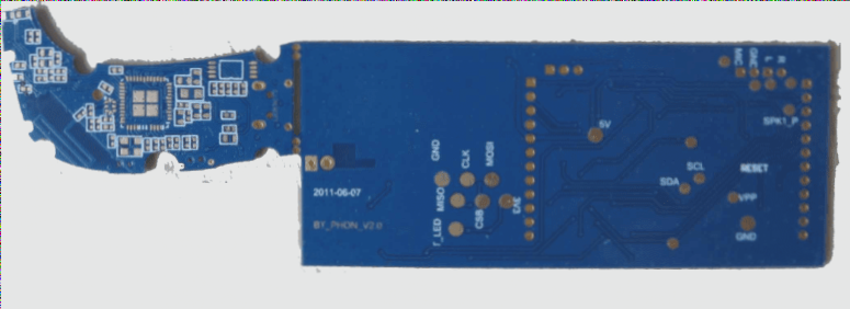
1. In a high-speed PCB system, impedance mismatch on the transmission line can cause signal reflection, resulting in distortion such as overshoot, undershoot, and ringing.
2. When the delay (T_D) of the transmission line exceeds 20% of the signal rise time (T_R), the reflected signals become significant, potentially leading to signal integrity issues.
3. To mitigate reflection, resistors can be used: connect a resistor in series at the driving end to match the source impedance with the transmission line impedance, or connect a resistor in parallel at the receiving end to match the load impedance with the transmission line impedance, thereby reducing the source or load reflection coefficient to zero.
4. Common termination methods include series termination, simple parallel termination, Thevenin termination, RC network termination, and diode termination. These methods will be analyzed in detail below.

(1) Series Termination Series termination involves placing a resistor RS as close as possible to the source end to match the impedance of the signal source, achieving a reflection coefficient of zero. This suppresses signal reflections from the load, ensuring they are not reflected back from the source end. The series resistor RS should equal the transmission line impedance Zo minus the output impedance ZS of the driving source (RS = Zo – ZS). Typically, RS is chosen between 15 and 75Ω, with 33Ω being common. The advantage of this method is that only one termination resistor is needed per line, avoiding the need for a DC power supply and thus minimizing power consumption. It also provides current limiting for high capacitive loads, which helps reduce ground bounce noise. However, due to the voltage divider effect, the voltage at the midpoint of the trace is only half of the source voltage, making it unsuitable for driving distributed loads. Additionally, the series resistance increases the RC time constant, slowing down the load, which is problematic for high-frequency signals like high-speed clocks. It is crucial to place the series resistor as close as possible to the output of the source driver and avoid using vias, as they introduce capacitance and inductance.
(2) Parallel Termination Also known as DC parallel termination, this method involves connecting a termination resistor Rp (where Rp = Zo) to the receiver end of the wiring network, pulling it down to ground or up to the DC power supply to achieve matching and eliminate reflections at the load. The advantage is its simplicity and ease of implementation, but it consumes DC power, making it unsuitable for portable devices requiring low power consumption. Pulling up to power can enhance the driver’s capability but raises the signal’s low level, while pulling down to ground improves current sink capability but lowers the signal’s high level.
(3) Thevenin Termination Thevenin termination employs a voltage divider with a pull-up resistor Rpl and a pull-down resistor Rp2 to create a termination resistor that absorbs reflections. The equivalent impedance of the Thevenin termination must match the characteristic impedance Zo of the transmission line. The selection of Rpl and Rp2 should avoid inappropriate load voltage reference levels for high and low logic transitions. The ratio of Rp1 to Rp2 affects the drive currents for logic high and low. If Rp1 equals Rp2, the drive requirements for both logic levels are the same; if Rp1 is greater than Rp2, more current is required for logic high. Thevenin termination’s advantages include its compatibility with distributed loads, complete reflection absorption, and the ability to set the line voltage when no signal is driving the line. It is particularly suited for bus use but results in continuous DC current flow from the power supply to ground, causing power dissipation and potentially reducing noise margins unless the driver provides ample current. This method is well-suited for high-speed backplane designs, long transmission lines, and large loads by keeping the load voltage near the switching point.
(4) RC Network Termination Also known as AC load termination, this method uses a series RC network to provide termination impedance and eliminate reflections at the end of the network. The termination resistance Rp should match the transmission line impedance Zo, and the capacitor Cp should be chosen to ensure the RC time constant exceeds twice the propagation delay (RpCp > 2TD), typically using 0.1μF multilayer ceramic capacitors. For specific designs, capacitance values are determined by simulation. The benefit of AC termination is that the capacitor blocks the DC path, avoiding additional DC power dissipation while allowing high-frequency energy to pass through and acting as a low-pass filter. However, the RC time constant slows down the signal, and additional resistors and capacitors consume board space and increase cost.
(5) Diode Termination In diode termination, one diode is connected in series between the end of the transmission line and the power supply Vcc, and another diode is connected in series between the end of the transmission line and ground. Schottky diodes are often used due to their low turn-on voltage. Unlike other termination methods, diode termination does not aim to match the transmission line’s characteristic impedance to eliminate reflections. Instead, it stabilizes the voltage when the receiver voltage overshoots. Although it prevents overshoot, it does not eliminate reflections and may slow down reflections on high-speed signals. To leverage this technique’s benefits, it can be combined with other termination methods on a PCB.
2. When the delay (T_D) of the transmission line exceeds 20% of the signal rise time (T_R), the reflected signals become significant, potentially leading to signal integrity issues.
3. To mitigate reflection, resistors can be used: connect a resistor in series at the driving end to match the source impedance with the transmission line impedance, or connect a resistor in parallel at the receiving end to match the load impedance with the transmission line impedance, thereby reducing the source or load reflection coefficient to zero.
4. Common termination methods include series termination, simple parallel termination, Thevenin termination, RC network termination, and diode termination. These methods will be analyzed in detail below.

(1) Series Termination Series termination involves placing a resistor RS as close as possible to the source end to match the impedance of the signal source, achieving a reflection coefficient of zero. This suppresses signal reflections from the load, ensuring they are not reflected back from the source end. The series resistor RS should equal the transmission line impedance Zo minus the output impedance ZS of the driving source (RS = Zo – ZS). Typically, RS is chosen between 15 and 75Ω, with 33Ω being common. The advantage of this method is that only one termination resistor is needed per line, avoiding the need for a DC power supply and thus minimizing power consumption. It also provides current limiting for high capacitive loads, which helps reduce ground bounce noise. However, due to the voltage divider effect, the voltage at the midpoint of the trace is only half of the source voltage, making it unsuitable for driving distributed loads. Additionally, the series resistance increases the RC time constant, slowing down the load, which is problematic for high-frequency signals like high-speed clocks. It is crucial to place the series resistor as close as possible to the output of the source driver and avoid using vias, as they introduce capacitance and inductance.
(2) Parallel Termination Also known as DC parallel termination, this method involves connecting a termination resistor Rp (where Rp = Zo) to the receiver end of the wiring network, pulling it down to ground or up to the DC power supply to achieve matching and eliminate reflections at the load. The advantage is its simplicity and ease of implementation, but it consumes DC power, making it unsuitable for portable devices requiring low power consumption. Pulling up to power can enhance the driver’s capability but raises the signal’s low level, while pulling down to ground improves current sink capability but lowers the signal’s high level.
(3) Thevenin Termination Thevenin termination employs a voltage divider with a pull-up resistor Rpl and a pull-down resistor Rp2 to create a termination resistor that absorbs reflections. The equivalent impedance of the Thevenin termination must match the characteristic impedance Zo of the transmission line. The selection of Rpl and Rp2 should avoid inappropriate load voltage reference levels for high and low logic transitions. The ratio of Rp1 to Rp2 affects the drive currents for logic high and low. If Rp1 equals Rp2, the drive requirements for both logic levels are the same; if Rp1 is greater than Rp2, more current is required for logic high. Thevenin termination’s advantages include its compatibility with distributed loads, complete reflection absorption, and the ability to set the line voltage when no signal is driving the line. It is particularly suited for bus use but results in continuous DC current flow from the power supply to ground, causing power dissipation and potentially reducing noise margins unless the driver provides ample current. This method is well-suited for high-speed backplane designs, long transmission lines, and large loads by keeping the load voltage near the switching point.
(4) RC Network Termination Also known as AC load termination, this method uses a series RC network to provide termination impedance and eliminate reflections at the end of the network. The termination resistance Rp should match the transmission line impedance Zo, and the capacitor Cp should be chosen to ensure the RC time constant exceeds twice the propagation delay (RpCp > 2TD), typically using 0.1μF multilayer ceramic capacitors. For specific designs, capacitance values are determined by simulation. The benefit of AC termination is that the capacitor blocks the DC path, avoiding additional DC power dissipation while allowing high-frequency energy to pass through and acting as a low-pass filter. However, the RC time constant slows down the signal, and additional resistors and capacitors consume board space and increase cost.
(5) Diode Termination In diode termination, one diode is connected in series between the end of the transmission line and the power supply Vcc, and another diode is connected in series between the end of the transmission line and ground. Schottky diodes are often used due to their low turn-on voltage. Unlike other termination methods, diode termination does not aim to match the transmission line’s characteristic impedance to eliminate reflections. Instead, it stabilizes the voltage when the receiver voltage overshoots. Although it prevents overshoot, it does not eliminate reflections and may slow down reflections on high-speed signals. To leverage this technique’s benefits, it can be combined with other termination methods on a PCB.


