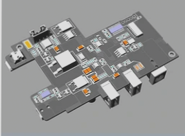
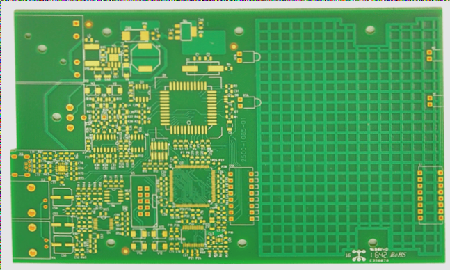
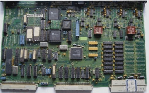
How to analyze defective PCBA electronic products and repaired BGAs is fundamentally a logical challenge. However, many novice engineers struggle to know where to begin when they receive defective PCBA products returned from customers or the market.
In fact, analyzing defective products is akin to a CSI or NSCI investigation. You need to employ scientific methods to uncover the truth step by step. First, gather (observe) evidence and identify potential causes of failure. While this may sound overly dramatic, it’s essential to hypothesize various possible causes, then verify them methodically to ultimately discover the truth. If feasible, documenting your findings can be beneficial.
Honestly, all engineering problems resemble the approaches outlined in [8D reports] and [Problem Solving]. The crucial element is how to proceed systematically. While this may seem tedious, a step-by-step approach can often help avoid overlooked details. In fact, you might even uncover unexpected insights, as the devil is often in the details.
Here are some steps and insights for analyzing defective PCBA products. These have been compiled from my own memory and experiences, so there may be some gaps or omissions. If any colleagues notice deficiencies, please feel free to share:
1. If the machine has not been disassembled, start with a visual inspection and functionality test to confirm that the product is genuinely defective. Occasionally, products returned by customers may actually be functioning correctly but are mistakenly identified as faulty.

This issue may arise from a problem with the customer’s power supply or other unrelated factors, rather than the product itself. However, some defects may only manifest after extended use or intermittently. The best approach is to power on the machine and allow the automatic program to run for at least one day, performing basic operations to see if the problem can be replicated.
Before receiving the defective product, it is ideal to inquire about the circumstances under which the defect occurred. This helps you understand the situation and assess the potential cause of the defect. Additionally, check for any signs of impact or damage from falling, as internal components can sometimes be harmed by physical shock.
2. If the defective item has been disassembled or consists solely of a circuit board, start with a visual inspection of the board. Some issues may stem from foreign objects, such as insects (reports have noted cockroaches or spider webs) finding a warm and humid environment in the machine, or accidental liquid contamination, with beverages like cola or coffee being common culprits for short circuits. These defects can often be identified through visual examination.
Using a microscope to inspect the circuit and components thoroughly is recommended. Conduct a detailed inspection without overlooking any clues.
3. After examining the PCB’s appearance, perform an electrical test and measure the CPU temperature. If the customer only returns the circuit board, functionality tests must follow the appearance inspection. This is similar to the previous point, but even with a complete machine return, electrical tests on individual boards can help identify which one is faulty, as some machines consist of multiple boards.
For boards that exhibit defects after some time, measure the main components’ temperatures (like the CPU). An abnormal temperature increase may indicate circuit issues. Conversely, if the temperature remains stable, it can help determine CPU activity.
4. Conduct circuit signal measurements to identify faulty parts and their locations. When appearance and basic electrical tests do not clarify the issue, deeper analysis is necessary. Here, electronic engineers typically use a multimeter and oscilloscope to check for non-conductive paths, shorts, voltage discrepancies, or timing issues in IC components. It’s essential to pinpoint potential fault locations.
5. If circuit measurements indicate a BGA issue, it’s crucial to ascertain whether it’s a short circuit or an open circuit, as well as identify potential solder joint locations. Electronic engineers are typically adept at this.
5.1 If the BGA shows a short circuit, an X-ray image can provide insights into the issue. However, if the product is a market return, the likelihood of a defect is low, as it should have passed basic electrical tests before leaving the factory. Some short-circuit problems are identifiable through X-ray, but may stem from flux and moisture, typically arising during environmental tests. Such issues are rare in customer returns, especially for fine-pitch BGAs.
5.2 If the BGA is open, several scenarios may exist:
5.2.1 The bonding wire within the IC package may be broken or dislodged, which can be assessed using X-ray.
5.2.2 The BGA solder balls could have open connections. Identifying the problematic solder ball is crucial, and X-ray can help, though it may not always reveal open or broken joints. For outer solder balls, optical methods like microscopy or endoscopes are beneficial, especially since the most common issues occur near the peripheral solder balls.
5.2.3 If none of the above methods yield answers, consider using the red dye penetration test or slicing. It’s essential to have experienced personnel conduct these analyses, as both methods cause permanent damage and should be used only as a last resort. If only one defective product is available, slicing is advisable, as it provides detailed insight into potential issues, including both BGA solder joints and PCB structure. Open circuits can occur not only in BGA solder joints but also in internal PCB sockets. Ensure that slicing targets the identified problematic BGA for efficient analysis.
If multiple boards exhibit the same defects, consider the red dye test, which is less detailed but can effectively identify cracks and issues across all solder joints in the BGA at once.
—
Let me know if you need any further adjustments!
In fact, analyzing defective products is akin to a CSI or NSCI investigation. You need to employ scientific methods to uncover the truth step by step. First, gather (observe) evidence and identify potential causes of failure. While this may sound overly dramatic, it’s essential to hypothesize various possible causes, then verify them methodically to ultimately discover the truth. If feasible, documenting your findings can be beneficial.
Honestly, all engineering problems resemble the approaches outlined in [8D reports] and [Problem Solving]. The crucial element is how to proceed systematically. While this may seem tedious, a step-by-step approach can often help avoid overlooked details. In fact, you might even uncover unexpected insights, as the devil is often in the details.
Here are some steps and insights for analyzing defective PCBA products. These have been compiled from my own memory and experiences, so there may be some gaps or omissions. If any colleagues notice deficiencies, please feel free to share:
1. If the machine has not been disassembled, start with a visual inspection and functionality test to confirm that the product is genuinely defective. Occasionally, products returned by customers may actually be functioning correctly but are mistakenly identified as faulty.

This issue may arise from a problem with the customer’s power supply or other unrelated factors, rather than the product itself. However, some defects may only manifest after extended use or intermittently. The best approach is to power on the machine and allow the automatic program to run for at least one day, performing basic operations to see if the problem can be replicated.
Before receiving the defective product, it is ideal to inquire about the circumstances under which the defect occurred. This helps you understand the situation and assess the potential cause of the defect. Additionally, check for any signs of impact or damage from falling, as internal components can sometimes be harmed by physical shock.
2. If the defective item has been disassembled or consists solely of a circuit board, start with a visual inspection of the board. Some issues may stem from foreign objects, such as insects (reports have noted cockroaches or spider webs) finding a warm and humid environment in the machine, or accidental liquid contamination, with beverages like cola or coffee being common culprits for short circuits. These defects can often be identified through visual examination.
Using a microscope to inspect the circuit and components thoroughly is recommended. Conduct a detailed inspection without overlooking any clues.
3. After examining the PCB’s appearance, perform an electrical test and measure the CPU temperature. If the customer only returns the circuit board, functionality tests must follow the appearance inspection. This is similar to the previous point, but even with a complete machine return, electrical tests on individual boards can help identify which one is faulty, as some machines consist of multiple boards.
For boards that exhibit defects after some time, measure the main components’ temperatures (like the CPU). An abnormal temperature increase may indicate circuit issues. Conversely, if the temperature remains stable, it can help determine CPU activity.
4. Conduct circuit signal measurements to identify faulty parts and their locations. When appearance and basic electrical tests do not clarify the issue, deeper analysis is necessary. Here, electronic engineers typically use a multimeter and oscilloscope to check for non-conductive paths, shorts, voltage discrepancies, or timing issues in IC components. It’s essential to pinpoint potential fault locations.
5. If circuit measurements indicate a BGA issue, it’s crucial to ascertain whether it’s a short circuit or an open circuit, as well as identify potential solder joint locations. Electronic engineers are typically adept at this.
5.1 If the BGA shows a short circuit, an X-ray image can provide insights into the issue. However, if the product is a market return, the likelihood of a defect is low, as it should have passed basic electrical tests before leaving the factory. Some short-circuit problems are identifiable through X-ray, but may stem from flux and moisture, typically arising during environmental tests. Such issues are rare in customer returns, especially for fine-pitch BGAs.
5.2 If the BGA is open, several scenarios may exist:
5.2.1 The bonding wire within the IC package may be broken or dislodged, which can be assessed using X-ray.
5.2.2 The BGA solder balls could have open connections. Identifying the problematic solder ball is crucial, and X-ray can help, though it may not always reveal open or broken joints. For outer solder balls, optical methods like microscopy or endoscopes are beneficial, especially since the most common issues occur near the peripheral solder balls.
5.2.3 If none of the above methods yield answers, consider using the red dye penetration test or slicing. It’s essential to have experienced personnel conduct these analyses, as both methods cause permanent damage and should be used only as a last resort. If only one defective product is available, slicing is advisable, as it provides detailed insight into potential issues, including both BGA solder joints and PCB structure. Open circuits can occur not only in BGA solder joints but also in internal PCB sockets. Ensure that slicing targets the identified problematic BGA for efficient analysis.
If multiple boards exhibit the same defects, consider the red dye test, which is less detailed but can effectively identify cracks and issues across all solder joints in the BGA at once.
—
Let me know if you need any further adjustments!


