The Rise of ESP32 in IoT Development
ESP32 has emerged as a leading choice for microcontrollers in recent years, capturing the interest of IoT developers and hobbyists. Packed with a wide range of features like capacitive touch sensors, Hall sensors, and various interfaces, the ESP32-WROOM module has become a favorite among tech enthusiasts.
Enhancing ESP32 Projects with Breakout Boards
The ESP32-WROOM module, with its castellated side pins, is ideal for prototyping and hobby projects. Learn how to create a minimal breakout board for the ESP32-WROOM, providing a solid foundation for your PCB designs and future projects.
Step 1: Integrating ESP32-WROOM Module in Proteus
Get started by adding the ESP32-WROOM module in Proteus for your project. Follow the tutorial to select the right module variant and incorporate it into your schematic for further development.
- Image:


Step 2: Establishing Essential Connections
Ensure proper functionality of the ESP32-WROOM by making essential connections such as power, ground, enable, and IO0. Learn how to set up these connections correctly for seamless operation of the module.
- Image:

Step 3: Adding Programming and Power Connectors
Integrate connectors for programming and power to enhance the functionality of your ESP32-WROOM setup. Follow the steps to incorporate terminal modes and connectors for efficient programming via UART.
- Image 1:
- Image 2:


Step 4: Implementing Power Regulation and LED Indicators
Enhance your ESP32 project with power regulation components and LED indicators for stable voltage control and visual power status cues. Follow the tutorial to incorporate these elements effectively.
Building a Power Regulation Circuit for ESP32 Module
Build a circuit with the provided components to ensure proper power regulation for your ESP32 module.
Step 5: Enhancing ESP32 Pins Connections
For unused pins on the ESP32 module, incorporate BIDIR terminals. Connect each unused pin to its corresponding header connector using CONN-SIL10, CONN-SIL18, and CONN-SIL6. This method offers versatility for accessing any remaining ESP32 pins in future endeavors.
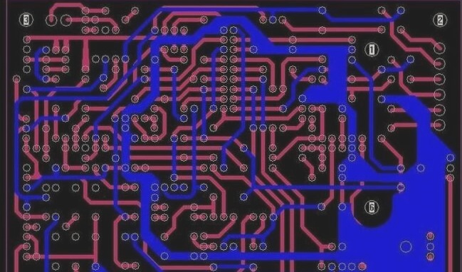
Step 6: Finalizing the Schematic
After placing and connecting all components, finalize your schematic by utilizing the layout editor. Access the editor by clicking on the designated icon below.
In the layout editor, arrange components on the board by selecting them from the “Component Window” and situating them within the layout workspace.