Printed Circuit Board (PCB) Design Best Practices
Ground Wire Design
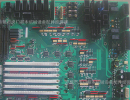
Electronic equipment heavily relies on printed circuit boards (PCBs) for assembly. A well-designed PCB is essential for ensuring the reliability of electronic devices. Improper PCB design, such as placing thin parallel traces too closely together, can lead to signal delays and reflection noise, impacting performance.
Key Considerations for Ground Layout:
- Single-Point vs. Multi-Point Grounding: In low-frequency PCB circuits (PCB), single-point grounding is preferred for frequencies below 1 MHz, while multi-point grounding is recommended for frequencies above 10 MHz. For frequencies between 1-10 MHz, ground wire length should not exceed 1/20th of the wavelength.
- Separate Digital and Analog Circuits: Keep high-speed digital and analog circuits separate, with isolated ground connections to minimize noise interference.
- Optimal Ground Wire Thickness: Thicker ground wires (>3 mm) are essential to maintain stable ground potential, timing signals, and noise immunity.
- Implement a Closed Ground Loop: Creating a closed ground loop in PCB designs with digital circuits enhances noise immunity, especially in systems with multiple integrated circuits or high power consumption.
By following these design principles, electronic devices can achieve optimal performance and reliability through efficient PCB grounding techniques.