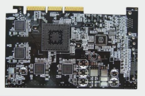
Grounding a PCB Board: Methods and Rules
Types of Grounding:
- Power Ground:
The power ground is crucial for completing the circuit in both AC and DC voltages. It ensures the current flows properly by connecting components to the ground. This type of grounding is commonly used in large electrical power systems and electronics, with connections earthed for safety.
- Signal Ground:
Signal ground handles analog or digital signals and may have separate connections from power grounds. It is vital in sensitive equipment and measuring instruments for signal return.
- Virtual Ground:
Virtual ground, often in operational amplifiers, matches the ground potential without direct connection. It tests operational amplifier functionality effectively.
- Surge and Lightning Protection Ground:
For dissipating high currents during surges or lightning strikes, a solid ground connection is essential. Welded to steel structures and earthed by rods and mesh, these grounds ensure safety by equalizing voltage differences.
- Grounding in Electric Power System:
Grounding practices in electrical systems vary by country but aim to provide safety while working on PCBs. Different codes indicate earthing arrangements to power sources, ensuring safety and functionality.
- Floating Ground:
When a solid ground connection is lacking, a floating ground can be used to prevent voltage determination in terminals and conductors. Isolation transformers and low voltage supplies enhance safety by separating ground systems and avoiding current grounding from the main supply.
Grounding Methods:
When grounding a printed circuit board, following specific methods is crucial for successful grounding of terminals, considering design practices and circuit applications.

PCB Grounding Techniques
In traditional PCB designs, components connected to the ground are linked through common ground traces. Here are some modern PCB grounding techniques:
1. Common Ground Plane
The common ground plane is a widely used practice in PCB design. It covers empty spaces on the board not occupied by components or traces, improving thermal characteristics and reducing electromagnetic interference.
2. Dedicated Ground Layer
Complex PCBs with multiple layers utilize a dedicated ground layer. Each component in the PCB connects to this ground layer for enhanced performance.
3. Grounding Electrical Power Systems
In electrical power systems, multiple connections lead to a common ground connection. Connections are linked to an earth bus bar, which connects to an earth conductor and further to an earth rod or mesh for effective grounding.
4. Equipotential Earthing or Grounding
Equipotential grounding ensures equal potential among all elements in the system, preventing shocks due to potential differences. Connecting equipment frameworks and metal pipes helps maintain the same potential across all conductive parts.
Grounding Best Practices
Follow these rules for effective PCB grounding:
- Leave nothing unattached: Fill empty spaces with copper or connect to the ground plane for efficient signal movement.
- Never slice up your ground layer: Avoid routing traces on the dedicated ground layer to prevent ground current loops.
- Always provide a common ground point: Ensure a common ground point for single or multi-layered electronic systems.
- Minimize service vias: Direct component grounds to the dedicated ground plane to reduce impedance.
- Grounding before routing: Properly ground the PCB before routing to ensure operational safety.
- Know where your currents are going: Monitor current paths in addition to signal pathways for stable power.
- Plan for dynamic variance between grounds: Consider dynamic variations between grounds for effective PCB performance.
Key Tips for Grounding a Printed Circuit Board
- Consider dynamic variance between grounds, especially for long-distance cables.
- Utilize low voltage differential signals, optical isolators, and common-mode chokes for better performance.
When planning your mixed-signal floor layout, ensure separation between the analog to digital converter and digital to analog converter. Keeping these areas distinct is crucial for efficient signal transmission within the printed circuit board.
Expert Advice on Grounding
Grounding a printed circuit board is a task that requires patience and expertise. It is essential to understand the different types, methods, and rules associated with grounding to ensure accurate results. Beginners can gain valuable experience by delving into the complexities of PCB grounding, paving their way to becoming professionals in the field.

