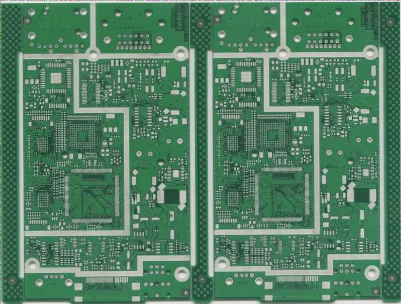
Everyone is familiar with PCBs, but do you truly understand their wiring? PCB wiring is often viewed as a foundational topic for every electronic engineer; however, many tend to focus solely on the connections while overlooking the arrangement of various components on the PCB.

1. Cross circuits are not permitted on printed circuits. For lines that may intersect, you can utilize two methods: “drilling” and “winding.” This means allowing a lead to “drill” through the space beneath other resistors, capacitors, or transistor pins, or “wind” around from one end of a lead that could cross. Regardless of circuit complexity, it’s crucial to simplify the design when necessary. Connecting with wires is permissible to address cross circuit issues.


2. Components such as resistors, diodes, and tubular capacitors can be installed using both “vertical” and “horizontal” methods. The vertical installation involves placing the component body perpendicular to the circuit board, offering the advantage of space-saving. In contrast, the horizontal method positions the component body parallel and close to the circuit board, providing enhanced mechanical strength. The hole pitch for these two mounting styles differs on the printed circuit board.

3. Grounding points for circuits at the same level should be positioned as closely as possible, with the power filter capacitor for that circuit also connected to its grounding point. Particularly, the grounding points for the base and emitter of a transistor should not be too far apart; excessive distance can lead to long copper traces that may introduce interference and self-excitation. Utilizing a “single-point grounding method” will result in better stability and reduced self-excitation.

4. The arrangement of the main ground wire must adhere strictly to the hierarchy of high frequency, intermediate frequency, and low frequency, following the order from weak current to strong current without arbitrary reversal. This guideline is especially critical for the grounding wire configurations of frequency conversion heads, regeneration heads, and frequency modulation heads. Incorrect arrangements can lead to self-excitation and operational failure. High-frequency circuits, like FM heads, typically employ large surrounding ground wires to ensure effective shielding.

5. Strong current leads, such as common grounds and power amplifier power leads, should be as wide as feasible to minimize wiring resistance and voltage drop, thereby reducing self-excitation caused by parasitic coupling.

6. Traces with high impedance should be kept as short as possible, while those with low impedance can be longer. High-impedance traces are prone to whistling and signal absorption, which can destabilize the circuit. Low-impedance traces include power cords, ground wires, and base traces without feedback components. The base trace of the emitter follower and the ground wires for the two channels of the radio should remain separate, forming distinct paths until they converge again; connecting two ground wires back and forth can easily lead to crosstalk and diminish separation. The above points summarize some experiences regarding wiring arrangements among various components on PCB circuit boards, and I hope they prove beneficial to all.


Let me know if you need anything else!

Leave a Comment

Contact

WellCircuits
More than PCB

Upload your GerberFile(7z,rar,zip)